Simple Class D Speaker Amp Using a MOSFET Driver
 Phil Pilgrim (PhiPi)
Posts: 23,514
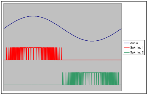
There have been several threads regarding speaker output for the Propeller. Most involve analog amplification of filtered DUTY-mode output from one of the counters. There's another kind of amplifier called "Class D" that sends PWM output directly to the speaker, letting the voice coil's inductance and speaker cone's physical inertia do all the filtering. It occurred to me that a MOSFET driver chip might have enough oomph to drive an 8-ohm speaker. If so, it would then be a simple matter of driving its inputs with the proper signals to drive the speaker differentially, H-bridge fashion:

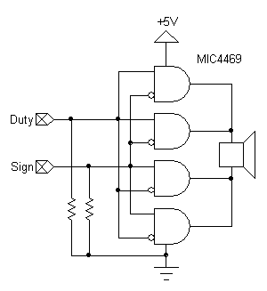
Here's the circuit I used. I selected a Micrel MIC4469 becasue it had some useful logic on its inputs. It also has built-in protection diodes on the outputs for inductive loads. Notice that two outputs from each side are paralleled to provide more current drive. The "sign" input basically selects which side of the speaker receives the DUTY modulation. When the sign is set (negative audio swing), the duty will be more than 50%. That's just right, because it goes into the inverting input of the lower half of the driver.

Here is the test program. It generates a sinewave, which my 6W 8-ohm speaker reproduced with very reasonable volume. It was loud enough to annoy my cat Browser from his top-shelf sleeping perch (photo below) and send him out the door. (He needs more exercise anyway.) The driver chip did not even get warm, which is one of the advantages of Class D amplification.
I tried connecting the MIC4469's Vdd pin to Vin and, as expected, the volume got much louder, but with some audible distortion. I have a feeling that there are inductive issues which cause the distortion that need to be addressed somehow. (Perhaps Beau can weigh in on this issue.) Anyway, it was an interesting experiment which proves the principle, at least, that minimal-component Class D audio amps are possible, given the right kind of output from the Prop.
-Phil
Addendum: I changed the code to make it a proper object and doubled the DUTY output level, effectively qudrupling the available output power. It made a big difference, and I didn't hear the distortion I did with the higher (Vin) supply voltage. I also changed the schematic to include pulldowns on the driver inputs. This will keep the driver in a quiescent state when the Prop pins are tri-stated, protecting the driver from a continuous over-current condition. For maximum protection, capacitively coupling the Prop outputs might also be recommended.
Addendum 2: I changed the source code once more to update the DUTY mode ouput at regular 200ns intervals (assuming 80MHz clock).
_
Post Edited (Phil Pilgrim (PhiPi)) : 7/4/2009 8:51:30 PM GMT
Here's the circuit I used. I selected a Micrel MIC4469 becasue it had some useful logic on its inputs. It also has built-in protection diodes on the outputs for inductive loads. Notice that two outputs from each side are paralleled to provide more current drive. The "sign" input basically selects which side of the speaker receives the DUTY modulation. When the sign is set (negative audio swing), the duty will be more than 50%. That's just right, because it goes into the inverting input of the lower half of the driver.
Here is the test program. It generates a sinewave, which my 6W 8-ohm speaker reproduced with very reasonable volume. It was loud enough to annoy my cat Browser from his top-shelf sleeping perch (photo below) and send him out the door. (He needs more exercise anyway.) The driver chip did not even get warm, which is one of the advantages of Class D amplification.
[b]CON[/b]

  [b]_clkmode[/b]      = [b]xtal1[/b] + [b]pll16x[/b]
  [b]_xinfreq[/b]      = 5_000_000

  duty_pin      = 0
  sign_pin      = 1

  sine          = $e000

[b]VAR[/b]

  [b]long[/b]  waveform[noparse][[/noparse]*64]
  [b]byte[/b]  cogno

[b]PUB[/b] demo | amplitude, i, phase, t, f

  [b]repeat[/b] i [b]from[/b] 0 to 63
    waveform[noparse][[/noparse]*i] := sin(i << 7) * 32767
  amplitude~
  start(duty_pin, sign_pin, @amplitude)
  f := clkfreq / 30000
  t := [b]cnt[/b]
  [b]repeat[/b]
    [b]waitcnt[/b](t += f)
    amplitude := waveform[noparse][[/noparse]*i := (i + 1) & 63]

[b]PUB[/b] start(dutypin, signpin, ampaddr)

  '' Start the class D output driver.
  ''   dutypin: Prop pin number (0 - 27) for DUTY output.
  ''   singpin: Prop pin number (0 - 27) for SIGN output.
  ''   ampaddr: Hub address of a LONG containing the instantaneous audio amplitude.
  stop
  |< dutypin
  |< signpin
  [b]return[/b] cogno := [b]cognew[/b](@classD, @dutypin) + 1

[b]PUB[/b] stop

  '' Stop the class D output driver.

  [b]if[/b] (cogno)
    [b]cogstop[/b](cogno - 1)
    cogno~

[b]PRI[/b] sin(x) : value

  '' Sine of the angle x: 0 to 360 degrees = $0000 to $2000

  [b]if[/b] (x & $fff == $800)
    value := $1_0000
  [b]elseif[/b] (x & $800)
    value := [b]word[/b][noparse][[/noparse]*sine][noparse][[/noparse]*-x & $7ff]
  [b]else[/b]
    value := [b]word[/b][noparse][[/noparse]*sine][noparse][[/noparse]*x & $7ff]
  [b]if[/b] (x & $1000)
    value := -value

[b]DAT[/b]

              [b]org[/b]       0

classD        [b]mov[/b]       amp,[b]par[/b]                 'Assumes A0 and A1 for output.
              [b]rdlong[/b]    dutymask,amp            'Get the duty pin mask.
              [b]add[/b]       amp,#4
              [b]rdlong[/b]    signmask,amp            'Get the sign pin mask.
              [b]add[/b]       amp,#4
              [b]rdlong[/b]    ampladdr,amp            'Get the amplitude address.
              [b]mov[/b]       [b]dira[/b],dutymask
              [b]or[/b]        [b]dira[/b],signmask

:loop         [b]add[/b]       phs,amp [b]wc[/b]              '[noparse][[/noparse]* 4] Add amplitude value to software counter phase.
              [b]muxc[/b]      [b]outa[/b],dutymask           '[noparse][[/noparse]* 4] Carry is duty output.

              [b]rdlong[/b]    new_amp,ampladdr        '[noparse][[/noparse]* 1 + 7] Get the next amplitude value.

              [b]add[/b]       phs,amp [b]wc[/b]              '[noparse][[/noparse]* 4] Add current amplitude value to software counter phase.
              [b]muxc[/b]      [b]outa[/b],dutymask           '[noparse][[/noparse]* 4] Carry is duty output.

              [b]shl[/b]       new_amp,#1 [b]wc[/b]           '[noparse][[/noparse]* 4] Multiply new amplitude value by 2, saving the sign in carry.
              [b]muxc[/b]      out,signmask            '[noparse][[/noparse]* 4] Set the sign value in out.

              [b]add[/b]       phs,amp [b]wc[/b]              '[noparse][[/noparse]* 4] Add current amplitude value to software counter phase.
              [b]muxc[/b]      [b]outa[/b],dutymask           '[noparse][[/noparse]* 4] Carry is duty output.

              [b]add[/b]       phs,new_amp [b]wc[/b]          '[noparse][[/noparse]* 4] Add new amplitude value to software counter phase.
              [b]muxc[/b]      out,dutymask            '[noparse][[/noparse]* 4] Carry is duty output: save in out.

              [b]nop[/b]                               '[noparse][[/noparse]* 4] Delay for constant 200ns pulse timing.
              [b]mov[/b]       [b]outa[/b],out                '[noparse][[/noparse]* 4] Output new duty and sign simultaneously.

              [b]mov[/b]       amp,new_amp             '[noparse][[/noparse]* 4] Now, set current amplitude to new amplitude.
              [b]jmp[/b]       #:loop                  '[noparse][[/noparse]* 4] Ad infinitum.
                                                '----
                                                '[noparse][[/noparse]*64] Clocks for loop, or four hub cycles.

phs           [b]res[/b]       1                       'Phase of the software counter.
amp           [b]res[/b]       1                       'Cog copy of amplitude.
new_amp       [b]res[/b]       1                       'Cog buffer for new amplitude.
out           [b]res[/b]       1                       'Buffer for outa.
dutymask      [b]res[/b]       1                       'Pin mask for duty output.
signmask      [b]res[/b]       1                       'Pin mask for sign output.
ampladdr      [b]res[/b]       1                       'Hub address of the instantanous audio amplitude.
I tried connecting the MIC4469's Vdd pin to Vin and, as expected, the volume got much louder, but with some audible distortion. I have a feeling that there are inductive issues which cause the distortion that need to be addressed somehow. (Perhaps Beau can weigh in on this issue.) Anyway, it was an interesting experiment which proves the principle, at least, that minimal-component Class D audio amps are possible, given the right kind of output from the Prop.
-Phil
Addendum: I changed the code to make it a proper object and doubled the DUTY output level, effectively qudrupling the available output power. It made a big difference, and I didn't hear the distortion I did with the higher (Vin) supply voltage. I also changed the schematic to include pulldowns on the driver inputs. This will keep the driver in a quiescent state when the Prop pins are tri-stated, protecting the driver from a continuous over-current condition. For maximum protection, capacitively coupling the Prop outputs might also be recommended.
Addendum 2: I changed the source code once more to update the DUTY mode ouput at regular 200ns intervals (assuming 80MHz clock).
_
Post Edited (Phil Pilgrim (PhiPi)) : 7/4/2009 8:51:30 PM GMT


Comments
▔▔▔▔▔▔▔▔▔▔▔▔▔▔▔▔▔▔▔▔▔▔▔▔
propmod_us and propmod_1x1 are in stock. Only $30. PCB available for $5
Want to make projects and have Gadget Gangster sell them for you? propmod-us_ps_sd and propmod-1x1 are now available for use in your Gadget Gangster Projects.
Need to upload large images or movies for use in the forum. you can do so at uploader.propmodule.com for free.
-Phil
-Phil
-Phil
▔▔▔▔▔▔▔▔▔▔▔▔▔▔▔▔▔▔▔▔▔▔▔▔
My Prop Info&Apps: ·http://www.rayslogic.com/propeller/propeller.htm
Due the armonic components for a high quality audio signal, I think you should turn the PWM period so short as possible, considering the max MOSFET capacity, and the bigger frequency you would like to play. I don't know if the prop could do this.
>>> I think you should turn the PWM period so short as possible... (Or better... do some math before, to calculate the correct PWM period)
@ Phil
What is the sinewave frequency that your demo plays ? 1Khz ?
▔▔▔▔▔▔▔▔▔▔▔▔▔▔▔▔▔▔▔▔▔▔▔▔
Regards.
Alberto.
The sine wave frequency is more like 400Hz. That's about the fastest I could generate in Spin using 64 samples per cycle. I used a sine wave to test because it's easier to hear any distortion than with something more complex. The minimum duty-mode pulse width from the driver itself is about 675ns, which seems to get filtered out adequately.
-Phil
-Phil
Post Edited (Phil Pilgrim (PhiPi)) : 7/4/2009 8:59:22 PM GMT
it seems to me that the mc4469 is not so common. Imho you could to the same with a 6 times Inverter.
On one side you can connect the PWM-signal and the other side is the polarity.
At zero crossing you would have to exchange the high/low pulse width durations.
chris
-Phil
But I'm shure, there can be something done with less.
For instance one could use a 74hc244 and connect the buffers parallel. Probably 2 capacitors will be needed to decouple the speaker. The current can be up to 140 mA.
▔▔▔▔▔▔▔▔▔▔▔▔▔▔▔▔▔▔▔▔▔▔▔▔
propmod_us and propmod_1x1 are in stock. Only $30. PCB available for $5
Want to make projects and have Gadget Gangster sell them for you? propmod-us_ps_sd and propmod-1x1 are now available for use in your Gadget Gangster Projects.
Need to upload large images or movies for use in the forum. you can do so at uploader.propmodule.com for free.
Post Edited (mctrivia) : 7/4/2009 7:41:59 PM GMT
I have quite a few 9A MOSFET drivers that work very well. They are UCC27322 from TI. If you need more current handling ability, give 'em a try.
EDIT: Also, Phil, I think those rise/fall times are a function of the load capacitance. The driver I mentioned above, has rise/fall times of about 20ns, but that's with a 10nF load. The rise/fall times you mentioned are for a 1nF load(datasheet). If you are only driving the speaker, and no capacitance, don't you think that these rise/fall times would probably be faster than listed in the datasheet? The propogation delay would still be the same, but that wouldn't matter too much if ALL drivers had a delay.
Post Edited (Philldapill) : 7/4/2009 8:11:19 PM GMT
-Phil
Post Edited (Phil Pilgrim (PhiPi)) : 7/4/2009 9:00:45 PM GMT