

PLEASE HELP with SERIN, newbie so close to breakthrough!!!
 reenignE
Posts: 3
reenignE
Posts: 3
I will admit I have made no contribution to this forum, however when I complete the first working version I will post what I have on the completed projects section.· First however I will need help with having my BS2e accept what I assume should be TTL data on PIO 3 from my bluetooth module (Bluesmirf).··
I`ve set every UART setting on both the Bluesmirf and Hyperterminal to 2400-8-N-1 and confirmed via hyperterminal command to/from Bluesmirf via bluetooth command `G` after connection. As you can see below my source for the SERIN command uses a baud value of 396 or 2400 after conversion.
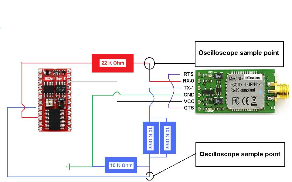
My basic stamp is part of ARobot (link below) and my bluetooth module is on the optional·expansion board that can ship with ARobot.· The bluetooth module is a Bluesmirf RP-SMA (links below)·and it outputs data from the Stamp to the Bluesmirf, over bluetooth to my PC's hyperterminal quite well.· I can even detect the data·received from the·PC on the TX of·the Bluesmirf·after my voltage divider. Moreover,·that data looks nearly IDENTICAL to the output from the stamp!?!?!
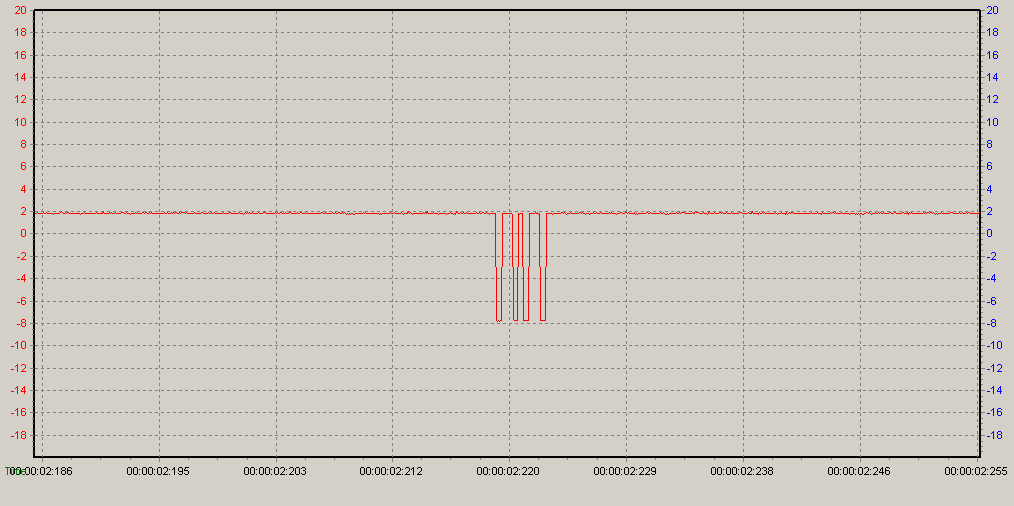
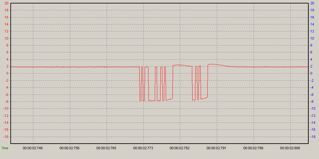
I've attached a basic schematc and screenshots of my oscilloscope readings (letter `k` from Bluesmirf, and I don`t remember what came from the Stamp); my source code is below.· Links to·ARobots and Bluesmirfs user guides will·precede my·source code below.
http://www.sparkfun.com/datasheets/Wireless/Bluetooth/rn-bluetooth-um.pdf· (data commands for Bluesmirf)
http://www.sparkfun.com/datasheets/RF/BlueSMiRF-RPSMA-Schematic.pdf· (Bluesmirf shematic)
http://www.arrickrobotics.com/arobot/guide.pdf·(PAGE 31 for ARobot·PINOUT / shematic)
SOURCE
' {$STAMP BS2e}
' {$PBASIC 2.5}
··· T2400············· CON····396
··· T9600············· CON····84
··· T16780············CON···· 16780···· '2400 baud, inverted, N, 1
··· T16468············CON···· 16468···· '9600 baud, inverted, N, 1
··· strData············VAR····· Byte
··· strOutput·········VAR······Byte(10)
··· S_IN··············· PIN······3 'pin 8 on the primary pinout - see ARobot User guide
··· S_OUT·············PIN····· 5 'pin 10 on the primary pinout
SEROUT S_OUT, T2400, [noparse][[/noparse]"Connected!", CR]· 'This is received by PC's Hyperterminal nicely!
Main:
DO
· SERIN S_IN, T2400, 10000, Main, [noparse][[/noparse]strData]
· '
· 'cycle the lights each loop cycle to provide visual feedback
· HIGH 10
· LOW 11
· PAUSE 2000
· LOW 10
· HIGH 11
LOOP
END
Please help a total electronics newb, I gave this a SERIOUS attempt before bothering you fine folks
p.s. this is like my 5th time using an oscilloscope ever so I don't know if that could be the problem. Also there is continuity between the TX on the Bluesmirf and PIO3 on the stamp, I checked with a DMM.
Best regards,
I`ve set every UART setting on both the Bluesmirf and Hyperterminal to 2400-8-N-1 and confirmed via hyperterminal command to/from Bluesmirf via bluetooth command `G` after connection. As you can see below my source for the SERIN command uses a baud value of 396 or 2400 after conversion.
My basic stamp is part of ARobot (link below) and my bluetooth module is on the optional·expansion board that can ship with ARobot.· The bluetooth module is a Bluesmirf RP-SMA (links below)·and it outputs data from the Stamp to the Bluesmirf, over bluetooth to my PC's hyperterminal quite well.· I can even detect the data·received from the·PC on the TX of·the Bluesmirf·after my voltage divider. Moreover,·that data looks nearly IDENTICAL to the output from the stamp!?!?!
I've attached a basic schematc and screenshots of my oscilloscope readings (letter `k` from Bluesmirf, and I don`t remember what came from the Stamp); my source code is below.· Links to·ARobots and Bluesmirfs user guides will·precede my·source code below.
http://www.sparkfun.com/datasheets/Wireless/Bluetooth/rn-bluetooth-um.pdf· (data commands for Bluesmirf)
http://www.sparkfun.com/datasheets/RF/BlueSMiRF-RPSMA-Schematic.pdf· (Bluesmirf shematic)
http://www.arrickrobotics.com/arobot/guide.pdf·(PAGE 31 for ARobot·PINOUT / shematic)
SOURCE
' {$STAMP BS2e}
' {$PBASIC 2.5}
··· T2400············· CON····396
··· T9600············· CON····84
··· T16780············CON···· 16780···· '2400 baud, inverted, N, 1
··· T16468············CON···· 16468···· '9600 baud, inverted, N, 1
··· strData············VAR····· Byte
··· strOutput·········VAR······Byte(10)
··· S_IN··············· PIN······3 'pin 8 on the primary pinout - see ARobot User guide
··· S_OUT·············PIN····· 5 'pin 10 on the primary pinout
SEROUT S_OUT, T2400, [noparse][[/noparse]"Connected!", CR]· 'This is received by PC's Hyperterminal nicely!
Main:
DO
· SERIN S_IN, T2400, 10000, Main, [noparse][[/noparse]strData]
· '
· 'cycle the lights each loop cycle to provide visual feedback
· HIGH 10
· LOW 11
· PAUSE 2000
· LOW 10
· HIGH 11
LOOP
END
Please help a total electronics newb, I gave this a SERIOUS attempt before bothering you fine folks
p.s. this is like my 5th time using an oscilloscope ever so I don't know if that could be the problem. Also there is continuity between the TX on the Bluesmirf and PIO3 on the stamp, I checked with a DMM.
Best regards,
Comments
· When using them with the Stamp i/o pins, you'll probably have to use the "inverted" settings for the SERIN and SEROUT.
· Alternatively, you can use i/o 16 which is the programming port which has the level shifting built in.
· Cheers,
▔▔▔▔▔▔▔▔▔▔▔▔▔▔▔▔▔▔▔▔▔▔▔▔
Tom Sisk
http://www.siskconsult.com
·
specifies the use of a voltage divider, would this be connected to the TX pin of the Bluesmirf since I'm running a 5VDC power supply?
THanks again for any help, I feel like I'm so close here
BEST REGARDS