Power Fluxuations
Hi there,
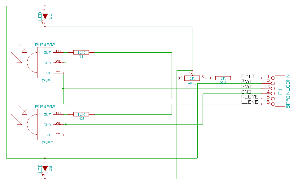
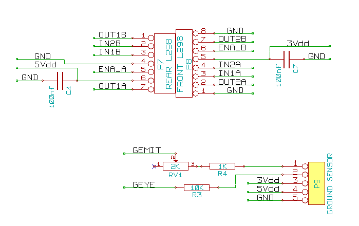
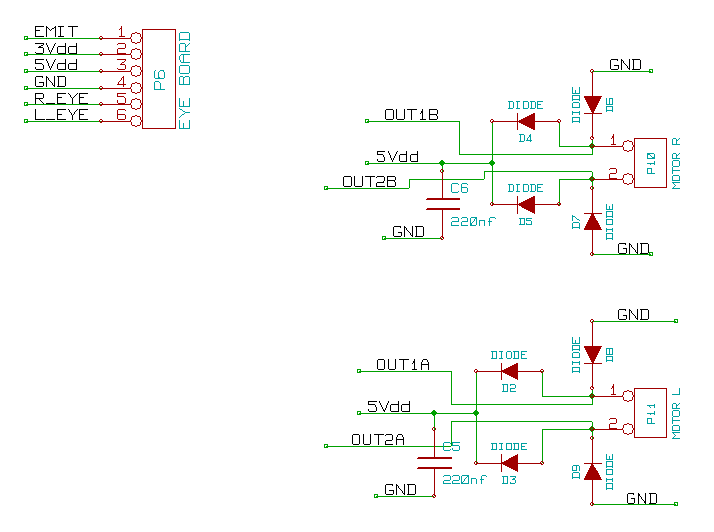
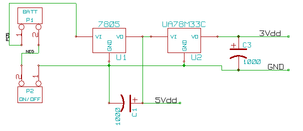
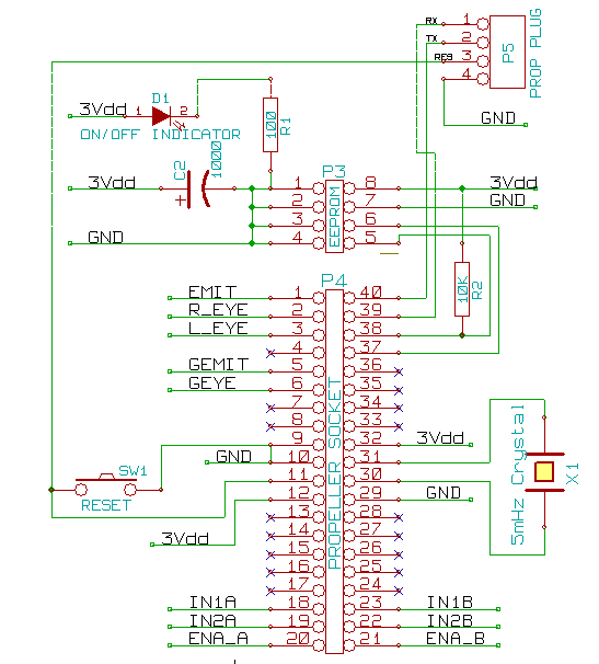
···· So, below is the schematics that i've drawn up and used to build my MTE1 (Mobile Tracked Explorer). I have prototyped·everything and have yet to have any problems but one. I am seeing a little bit of power fluxuations. Here is what is happening. I plug the battery in and the bot waits 3 seconds and then goes forward, backward, 360 left and 360 right then stops. The first time through you notice by the end that the movement is visibly slower. The next time through the movement is even slower, and so on, until it can barely turn in circles. But when you unplug the battery for a few seconds it starts all over with a strong movement down to slow movement.
Any ideas? I've been scratching my head about this one for awhile. Also, of course i have already ordered my PCBs and cannot cancel the order, so hopefully the design isn't too back, or i can jump anything i need to fix.
[noparse]:)[/noparse]
Thanks
-Mike
▔▔▔▔▔▔▔▔▔▔▔▔▔▔▔▔▔▔▔▔▔▔▔▔
======
······ I'll try everything once [noparse]:)[/noparse]


Comments
Another comment l298 has a logic supply of 4.5 to 7 volts. It isn't spec for a logic supply of 3.3V, you may have relibility problems with that. The way you have numbered the l298 pins is confusing since it doesn't match the datasheets numbering.
Post Edited (Timmoore) : 6/30/2009 3:03:45 AM GMT
I'm kind of bummed about the PCBs that i've ordered, for some reason when i prototyped this all on the breadboards, i never had a problem, that is why i ordered them. I'm going to see if i can talk them in to canceling my order. Cross your fingers.
-Mike
▔▔▔▔▔▔▔▔▔▔▔▔▔▔▔▔▔▔▔▔▔▔▔▔
======
······ I'll try everything once [noparse]:)[/noparse]
If anyone has any comments or suggestions i could use them fast. I believe i might be able to put my order, from batch PCB on hold only, MAYBE. But i will need to get updated gerbers to them.
-Mike
▔▔▔▔▔▔▔▔▔▔▔▔▔▔▔▔▔▔▔▔▔▔▔▔
======
······ I'll try everything once [noparse]:)[/noparse]
Does anyone have any suggestions on motor drivers, preferably a dual full bridge like the 293 and 298?
-Mike
▔▔▔▔▔▔▔▔▔▔▔▔▔▔▔▔▔▔▔▔▔▔▔▔
======
······ I'll try everything once [noparse]:)[/noparse]
I haven't used l298 yet, but I am most of the way through building a robot with 2 l298 but it has bigger motors and uses a 12V battery, should have the basics going this weekend.
-Mike
▔▔▔▔▔▔▔▔▔▔▔▔▔▔▔▔▔▔▔▔▔▔▔▔
======
······ I'll try everything once [noparse]:)[/noparse]
This is the code I use, you can see the check for direction change and set pwm to 0. Then change the direction pins and then set the new pwm value.
  repeat m from 0 to NumMotors-1
    if Motor & (|< m)                                   'for each motor command is for
      if (CurrentDirection[noparse][[/noparse]m] ^ (Speed & $8000)) OR (Braking[noparse][[/noparse]m] <> false)
        Braking[noparse][[/noparse]m] := false
        pwm.duty(PwmPin + PwmOffset[noparse][[/noparse]m], 0)              'set motor to coast if changing direction or was braked
      if (((Speed > 0) & |<m) ^ (Reverse & |<m))        'Calculate In Pins for correct direction
        SetIn(m, false, true)
      else
        SetIn(m, true, false)
      pwm.duty(PwmPin + PwmOffset[noparse][[/noparse]m], (||Speed)<#MAX_SPEED) 'set pwm duty cycle
      CurrentDirection[noparse][[/noparse]m] := Speed & $8000              'Save new direction
Its probably a side effect of motor noise, if you can reduce the motor noise more, you can probably remove the delays - the delays are spreading the time of the major current switching.
One other note - if you have servos as well, make sure your servo cables run well clear of the motor cables, the cross interference can be bad. You can get a lot of servo jitter.
After i know for sure my setup is working properly i would be finishing my program and implementing my PWM.
-Mike
▔▔▔▔▔▔▔▔▔▔▔▔▔▔▔▔▔▔▔▔▔▔▔▔
======
······ I'll try everything once [noparse]:)[/noparse]
Anyone have any other ideas besides getting another motor driver. I have had no luck getting samples of the L293D, although i can get L298N/HN all day long. If anyone knows of an easier to find driver that would be nice to. It really is going to irritate me if i have to pay $12 shipping for a $1-2 part. I have taken apart and rebuilt this circuit many times now, but the funny thing is that I have used this exact setup before without any of these problems. I have never had random restarts like this and absolutely never had power fluxuations (visible changes to motor speed).
▔▔▔▔▔▔▔▔▔▔▔▔▔▔▔▔▔▔▔▔▔▔▔▔
======
······ I'll try everything once [noparse]:)[/noparse]
MOTOR INFO:
MOTOR: GM9 (Gear Motor 9 @ solorbotics.com)
RATIO : 143:1
UNLOADED CURRENT (3v): 50mA
UNLOADED CURRENT (6V): 52mA
STALL CURRENT (3V) : 400mA
STALL CURRENT (6V) : 700mA
MY BOT INFO:
3.3v Regulator (UA78M33C I beleive): Running to PROP, L298 Logic v, 3 indicator LEDs (5mm), EEPROM, 2 IR Emitters
5v Regulator (7805): Running to IR Detectors
(TRIED)2nd 5v Regulator (7805): Running only to L298 output v, and positive side of motor/diode setup. (I've treid running this second 5v regulator to make sure all current
from this regulator went to motors).
(TRIED)Instead of the 2nd 5v Regulator, running straight battery connection through a capacitor/forward biased diode to L298 output v and motor/diode setup. Both options
yielded the same result, frequent brownouts.
BATTERY: 12v (6x AAA batteries)
First let me see if i understand everything correctly. Firstly, i have built a small stand, which allows me to run the bot without it moving around. The tracks are up off the table so i can test all functions. I realize that there is no load on the motors because it is sitting above ground. This would be the unloaded current i would assume. At this point i think the current through motors should be 5v (or battery v) @ 50-54mA. Now because i am now running straight off the battery voltage, about 12v Iam assuming the motor currents would go up by about another 400-600mA for stall current, is this correct?
The L298 should put out a max of 2A per channel, but, it is my understanding that unless the motors would have to actually try pulling that much current right? So in my mind, the motors, running on around 11v (because of the v-drop after the forward biased diode) should be only drawing right over 1 amp per motor, which the L298 should be able to handle, and, since the connection is straight from the battery (not the regulator rated at 1.5A) should be able to handle as well right? Now lets say i was still running off the regulator, the motors @5v would be running about 600mA x 2 motors = 1.2A max, which should also be ok because the regulator is rated to 1.5A, right? This is where i run in to trouble, because theoretically it should work without a problem, and it has in the past. But now, after having to pull everything apart when reconstructing the chassis, i'm having the brownout problem.
To help me, i have taken EVERYONES suggestions and ordered a few items. I have more 5v, 6v, 8v, 12v, and 15v regulators comming. I believe on this next redesign i will be using 2x 9v Battery packs = 18v regulated to whatever i will be using. Also, i have ordered 3 L293D's, which, i'm a little confused about, because looking at the datasheet it looks like max they will run 600mA per channel, which I will be running right on the verge of overheat and powerdown with my motors, but everyone seems to suggest them.
Now to more questions, when i do my redesign (once i get all my parts in), running 18v, or 2 9v packs. Should i indeed run 18v? or should i run 2 seperate power blocks, one for logic (prop, logic side of L298/L293D) and one for motors? Being that my motors are geared down to 143:1, they run pretty slow, with limited climing power at 5v, I would at least like to run them at 8v. Now the 8v regulator suggests running voltage of +2, meaning i would need at least a 10.5v power supply for regulating my 8v, that was why i thought of using my 18v, plus the extra mAh.
Well that was a mouthfull, i'm sure i have more questions, but hopefully soemone will answer some of these, or at least let me know if i'm understanding everything correctly.
-Michael Morris
▔▔▔▔▔▔▔▔▔▔▔▔▔▔▔▔▔▔▔▔▔▔▔▔
======
······ I'll try everything once [noparse]:)[/noparse]
Also, keep in mind that batteries and other power sources also have their own internal resistance. For the AAA batteries you are using that resistance is fairly high. They were intended for use in low current devices that are on for long periods of time like TV remote controls. You would be better of using AA or C cells designed for battery operated tools.
The driver IC's need to be matched to the peak and continuous currents your motors will draw at the voltage your batteries provide. If you provide 12V batteries and the motor stall current is 1.4A then the IC needs to be able to handle that current.
The battery voltage you use should be matched to the voltage you need to drive the motors. If the motors are rated for 12V then a 12V battery would be a good choice. The battery also has to be able to supply the current to drive the motors for a reasonable length of time. If your 2 motors need 2A each to move the robot, and you want the robot to be able to run for an hour on a charge you would need at least a 4AH battery. That is a battery that will put out 4Amps for 1 hour before needing to be recharged.
You can use batteries with a higher voltage than the motors are rated for but you need control circuitry such as PWM to limit the current and power dissipation to levels that will not damage the motors and driver circuits.
I have built several systems using variations of this and they work very reliably.
I have been playing around with different setups, now, and when i added another 9v to the mix (17-18v) it seems to have enough power not to brown out. But i quickly realized that the AAA batteries will not suffice. I will be finding alternate solutions to the battery, but first, let me say that running the motors i have on straight 17v is a little fast, and may be damaging the motors i think. Like i said above i have some different regulators and a few L293s on the way. While testing, the motors have enough torque and speed to suffice what i want at about 8-9v. So, the 8v regulator or the 12v that is on the way will do for the motors, but i beleive i will have to use a seperate regulator for each motor correct? The regulator is still only rated to about 1.5A, which would be just over the current for one motor. I think that is my main problem, the regulation of power through the driver to the motors. The L298 and the L293 are pretty alike, except for current of course. The problem i see is that there is one power source for both channels. If i run 2 regulators (8v/12v @ 1.5A each) and run both outputs to the L298/L293 does the current add upon itself? Meaning I know that running with 8 or 12v I will need current for both motors, but they will cause one regulator to shut down, so can i run 2 of them to the L298/L293? That is the reason i keep getting confused when people tell me to use a different motor driver, the L298 specs say 2A per channel, whereas the L293 is saying 600mA per channel, which @ 8-12v would already be surpassed.
Also, when i bumped up the voltage to the 18v there were no resets or brownouts until i visibly saw that the batteries were getting weak.
-Michael Morris
▔▔▔▔▔▔▔▔▔▔▔▔▔▔▔▔▔▔▔▔▔▔▔▔
======
······ I'll try everything once [noparse]:)[/noparse]
If you need power for a robot or other portable device you substitute batteries for the transformer and bridge rectifier, which provides a smooth DC as input for the capacitors and regulators.
In both cases the rest of the circuit is the same.
In your case I would power the motors directly off a 9 or 12 volt battery pack. No regulators are required. That is what the L298 is for. It can be pulse width modulated to regulate the motor speed.
In your application NiCad or NiMH AA cells may be the best choice. They are relatively inexpensive, easily obtained, and store a reasonable amount of energy ( 2 to 3 AH ). You would need 8 for 9.6V and 10 for 12V. The other option is a power tool battery of some type.
With a battery pack instead of a transformer/rectifier you do not need C1 but it is a good idea to include it to reduce noise from the motor. C2 should be at least 1000uF. If you have a 12V battery pack C2 should have about 11.3V on it and the voltage can drop quite a bit before it affects the 5V regulator. A switching regulator is the best choice for the 5V regulator.
D2 and C5 are not needed unless you are running servos or similar devices from the 5V supply. The 3.3V regulator can be a linear since it is only dropping 1.7V at relatively low current.
I am running off a 12V NiMH battery, the same as I use in another robot. The motors I am using I also use in the same other robot. I also use the prop protoboard in both robots. The differences are
1. Motor controller 2x L298, MC33887
2. 4 motors/2 motors - these motors are larger than the ones you are using 700ma non-load and 3.5A stall.
3. Larger robot (16"x16")(l298,4 motors) / smaller robot (8"x4")
The smaller robot using the MC33887 doesn't have reboot issues. The pwm control is very smooth, from pwm ratio to motor speed.
The larger robot using 2x L298 I am seeing reboot issues, also the pwm control is very non-linear, the pwm ratio to motor speed has a large gap at the lower end where the motors dont run. The battery goes to the 2x l298 directly and in parallel to the prop proto power in.
This was with a partly discharged battery, so I am recharging it and trying again.
There is 1 easy fix for this problem - use 2 batteries, 1 for the motors and 1 for the electronics.
Now i am rebuilding my one motor that now lights up when run (its also running visibly alot slower now). I soldered up a quick 15v battery using 3, 700mah rechargable 4.8v battery packs from handheld radios, intending to run my bot off of this, but forgot that one motor was disconnected.
TIMMOORE, mine is having the same problems that you seem to be having with your small robot i think. After all these problems i'm having i'm going to try just using 2 batteries like your saying. I am kind of leery about using the L293 because of the current that my motors will run will be a little over what the L293 can put out each channel. That is why i went with the L298, i thought i was doing the right thing by going with what could put out the current i required, but now i'm having all these issues. If 2 batteries is what it's going to take then i'll do it. I just hate to put extra weight in this thing, and trying to find room for an extra few battery packs is gonna be tought too. I can't run these motors on 5v because it has no speed or torque to clime over things in its path. I've found that about 8v or 10v is gonna be good. I think i'll use the 8 or 10v regulator like i said and use this 15v battery that i made to just motors.
Now using a second battery just for the motors includes the L298 correct. I will need to put the posotive battery to the motor/diode setup along with the Motor Output Voltage pin on the L298/L293 right?
-Mike
▔▔▔▔▔▔▔▔▔▔▔▔▔▔▔▔▔▔▔▔▔▔▔▔
======
······ I'll try everything once [noparse]:)[/noparse]
Look at figure 6 the bidirectional dc motor control in the l298 data sheet.
Oh, and BTW, I must have damaged some windings in the motor because it sparks and carries on, but the brushes are perfect, a little scorched but i wiped that off and put some more of the grease on them. I'm going to contact Solarbotics because i'm sure that is not suppose to happen and get some more motors. I even tried to get it to happen to another spare motor (same gm9 standard motor, without gear reduction) and i can't get it to spark and act like that one.
-Michael Morris
▔▔▔▔▔▔▔▔▔▔▔▔▔▔▔▔▔▔▔▔▔▔▔▔
======
······ I'll try everything once [noparse]:)[/noparse]
-Mike
▔▔▔▔▔▔▔▔▔▔▔▔▔▔▔▔▔▔▔▔▔▔▔▔
======
······ I'll try everything once [noparse]:)[/noparse]
Most of the regulators are spec'd at like 1A to 1.5A
-Mike
▔▔▔▔▔▔▔▔▔▔▔▔▔▔▔▔▔▔▔▔▔▔▔▔
======
······ I'll try everything once [noparse]:)[/noparse]
John Abshier
My motors @ 5v will need 1.2aH roughly, and @ 8v will need roughly 2AH. I will buy enough batteries to first make 5v packs test them on the motors then if i need solder on a few more for 8v packs. Also, i will make a seperate battery pack, either 5v or 8v, for the electronics that will run the prop, object detections, etc. All the batteries required for both packs will still be under $30 + shipping, very very doable. Does this sound like the right way to go.
Also, i do have to have some way of charging these packs back up. Does anyone have a reliable circuit for charging batteries through 110vac of the wall? I've never built a battery charger except for a small <9v charger using another 9v battery, which actually worked great.
Again thank you everyone for all of your help and support, and sorry it takes me a little bit to understand the simple concepts that you are all relaying to me.
-Michael Morris
▔▔▔▔▔▔▔▔▔▔▔▔▔▔▔▔▔▔▔▔▔▔▔▔
======
······ I'll try everything once [noparse]:)[/noparse]
1.5v / 2.7 ohm = 555ma (which is about the same as the motor that came with my gearboxes running at 5v)
being that space is an issue, would it be better for me to find small motors that are measuring about 2.5-3ohm so that i would use less batteries?
The rechargable batteries that i got have solder tabs (for making a battery pack) and are 1.2v @1000mah. 2 of them would be 2.4v
2.4 / 2.7ohm - 888mah
···················x···2 motors
················
··················· 1.777777mah (batteries max out at 2000mah/2A) PERFECT right?
-Mike
▔▔▔▔▔▔▔▔▔▔▔▔▔▔▔▔▔▔▔▔▔▔▔▔
======
······ I'll try everything once [noparse]:)[/noparse]
Post Edited (morris4019) : 7/8/2009 6:40:09 PM GMT
The manufactures should have the discharge rate curves as well.
-Mike
▔▔▔▔▔▔▔▔▔▔▔▔▔▔▔▔▔▔▔▔▔▔▔▔
======
······ I'll try everything once [noparse]:)[/noparse]
http://www.zbattery.com/NiCad-AA-1000mAh-Rechargeable-Battery-with-Solder-Tabs;jsessionid=0a01054f1f431dc48bf3bf214bc9b592e6984c111e5e.e3eTaxiNaN0Te34Pa38Ta38Ochn0
I bought 14 of these, figuring i would at most make 2 packs of 7 or so.
-Mike
▔▔▔▔▔▔▔▔▔▔▔▔▔▔▔▔▔▔▔▔▔▔▔▔
======
······ I'll try everything once [noparse]:)[/noparse]
-Mike
▔▔▔▔▔▔▔▔▔▔▔▔▔▔▔▔▔▔▔▔▔▔▔▔
======
······ I'll try everything once [noparse]:)[/noparse]