

** Question: Expand 18 Potentialmeter by using 74HC595 or 74HC165? **
 efly
Posts: 34
efly
Posts: 34
Hi all,
·
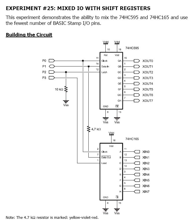
I have a control project which need to input total 18 numbers of potentialmeter at the same time, at first I am thinking using chips set (74HC595 & 74HC165) I/O expansion method. <Picture 01>
·
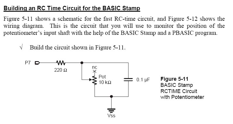
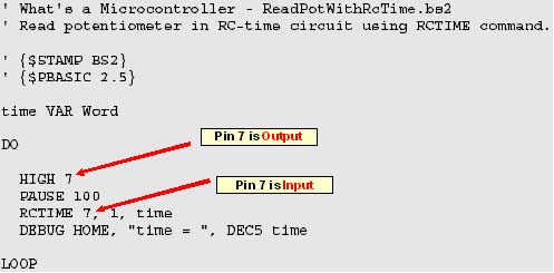
However, after I connected all circuit I really don’t have any idea since the general RCTime· Porgram at first set Pin 7 to high (as a output) then in RCTIME line command consider Pin 7 is input, how can I mix the (Pin7e-after expand, for example)·as 74HC595 is input and 74HC165 is output at the same time….?
·
Could some Parallax experts have any good idea?
Many thanks.· ·
·
Efly
Post Edited (efly) : 6/28/2009 5:01:17 PM GMT
·
I have a control project which need to input total 18 numbers of potentialmeter at the same time, at first I am thinking using chips set (74HC595 & 74HC165) I/O expansion method. <Picture 01>
·
However, after I connected all circuit I really don’t have any idea since the general RCTime· Porgram at first set Pin 7 to high (as a output) then in RCTIME line command consider Pin 7 is input, how can I mix the (Pin7e-after expand, for example)·as 74HC595 is input and 74HC165 is output at the same time….?
·
Could some Parallax experts have any good idea?
Many thanks.·
·Efly
Post Edited (efly) : 6/28/2009 5:01:17 PM GMT
658 x 775 - 59K
796 x 424 - 49K
497 x 245 - 25K
Comments
Here's some info: psurobotics.org/wiki/index.php?title=ADC0838
Do a web search for "ADC0838 Stamp" for other info
Post Edited (Mike Green) : 6/28/2009 5:36:43 PM GMT
Thanks for your valued advice, I will do some study on ADC and hopefully will suceed.·
Efly
I found that it might help to using 8-Channel 12-Bit A/D Converter (MCP3208) in order to reduce the Basic Stamp input pin number for above project, however, does anyone have any sample circuit connection diagram between Basic Stamp 2 and·MCP3208 since I cannot find it on the parallax page as it only provide the datasheet detail.
http://www.parallax.com/Store/Components/AllIntegratedCircuits/tabid/154/List/1/ProductID/573/Default.aspx?SortField=ProductName%2cProductName
Many thanks.··
Efly
Sample code attached.
The .VSD file is a Microsoft Visio file I made for the schematics, but the datasheet is pretty clear on this.
▔▔▔▔▔▔▔▔▔▔▔▔▔▔▔▔▔▔▔▔▔▔▔▔
Don't worry. Be happy