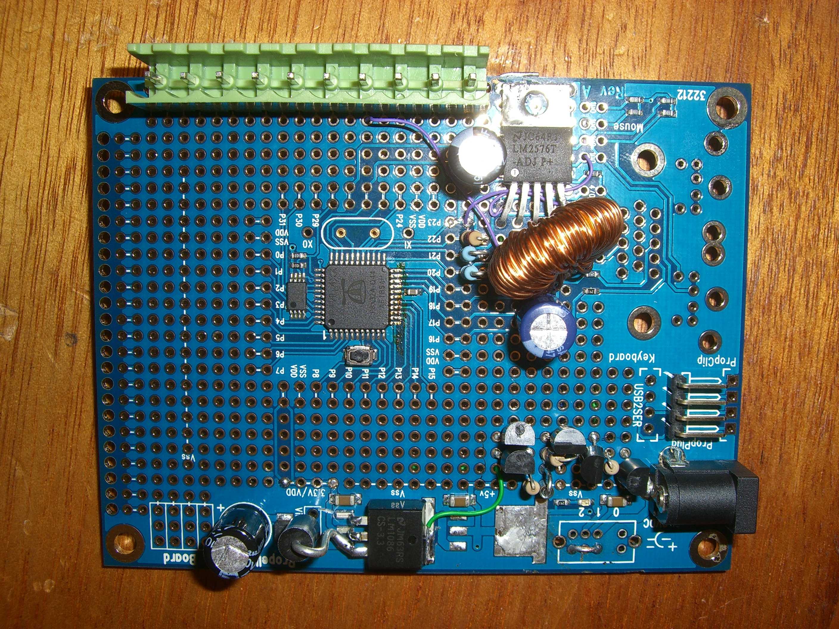
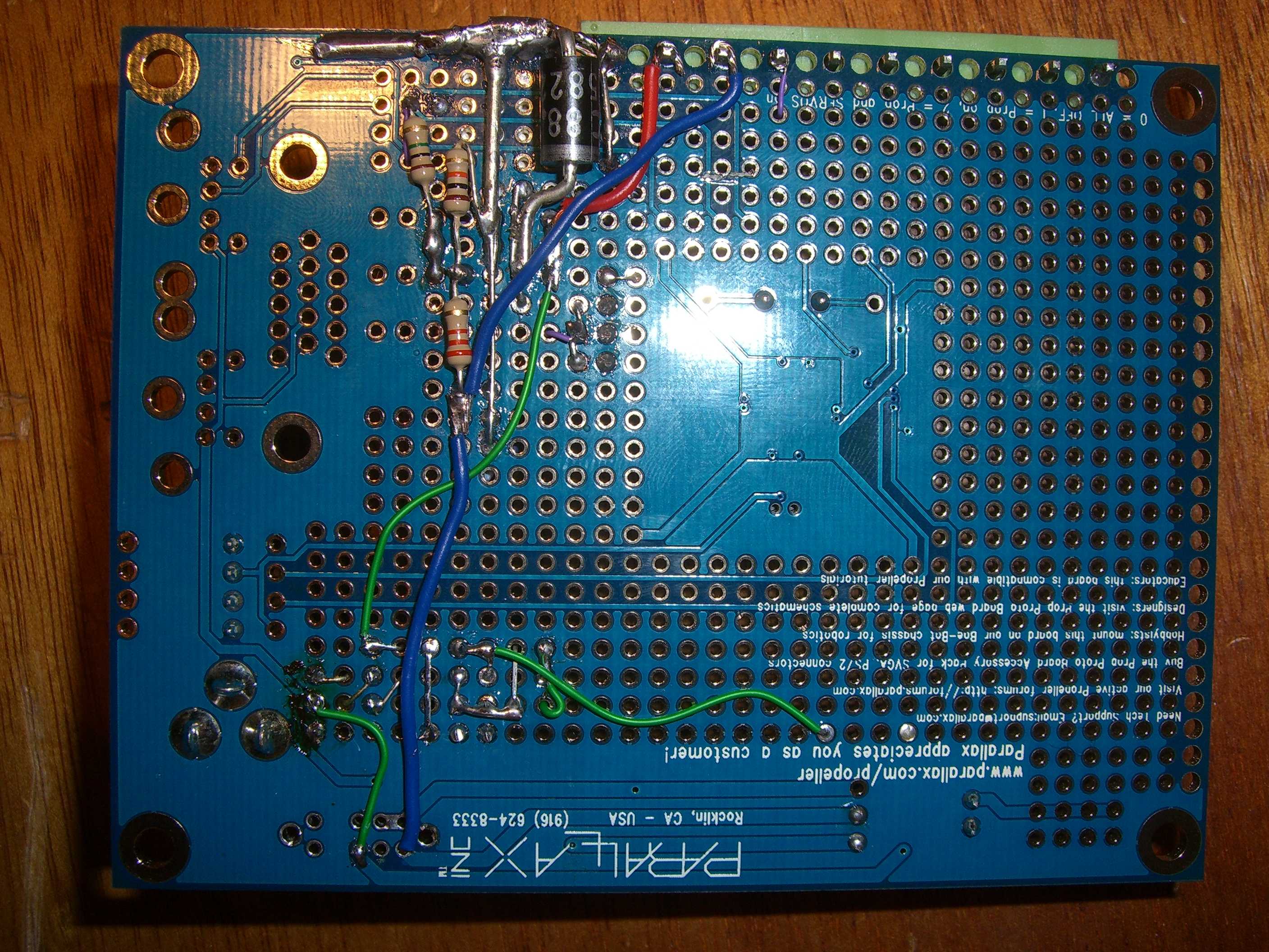
Protoboard modified for automotive use
I decided it was time to get a propeller into my car, and to do this I had to modify the power supply on the protoboard slightly as I wanted to run some servos and an LCD screen from the +5V rail. Hanging ~2A off the standard linear regulator with a 14.4V input was not an attractive proposition so I hacked the +5V reg off the board and installed an LM2576T-ADJ which I happened to have lying about.
I figured I could keep the prop powered with the 3.3V reg and switch the 5V rail on and off with a propeller pin, this would allow me to put it into low current standby when the vehicle was not running. Imagine my disgust when I discovered that I could not get less than 12.5mA current consumption with only one cog sitting in a one second waitcnt loop!
After reading the propeller datasheet pretty closely I figured I should be able to get the prop into some form of low power state, so something on the board must be consuming far more current than the propeller. Long story short, the LM1086 was consuming 10mA all by itself! Even when I supplied an external 3.3V to the power rail it still sat there chewing up 500% more power than the Propeller did. There was nothing for it but to isolate it from the circuit, but I wanted to be able to use it to power the propeller when the 5V rail was active as I have some things planned that will load the 3V3 raid pretty heavily when they are active. Enter a couple of paralleled 2N7000's and some switching hardware.
Now when the 5V rail is off, the propeller gets 3.0V from an LP2950CZ-3.0 and when the propeller pulls pin 23 low the +5V rail comes up and the on-board LM1086 brings the rail up to 3.3V. My idle power consumption has dropped to 2.1mA and I'm now happy as my propeller draws 1/10th of the power of my vehicle immobiliser when it's sitting idle, but the on board RTC cog continues to tick and it can wake up periodically and check all its sensors.
It's taken a little extra realestate on the proto-board (the LP2950 and associated switching circuits consumes a rectangle 4x9 holes), but I now have a Proto-board that will happily run all way at up to 30V, supply 3A on the +5V rail without breaking a sweat and idles at 2.1mA.
The low voltage reg and switching circuit could probably be improved or reduced in complexity with the right parts, but it's what I had handy [noparse]:)[/noparse]
▔▔▔▔▔▔▔▔▔▔▔▔▔▔▔▔▔▔▔▔▔▔▔▔
Missed it by ->" "<- that much!


Comments
▔▔▔▔▔▔▔▔▔▔▔▔▔▔▔▔▔▔▔▔▔▔▔▔
Toys are microcontroled.
Robots are microcontroled.
I am microcontroled.
If it's not Parallax then don't even bother. :-)
Mini-Din/PS2 connectors are for sale! 5 for $1! PM me if you wish to make an order.
Propeller SRAM TV driver winner: ==NOT COMPLEATED:·1·WEEK UNTIL ENDING TIME==
Post Edited (AJM) : 6/26/2009 1:03:16 PM GMT
Neat trick with the 0.2" Dinkle (or Phoenix or whatever) green connectors. Didn't realise it would be so easy to mount those to a proto board...
Looks like someone (or something) has been trying to solder something directly to your prop P11-19
tubular
Yeah the 0.2" connectors fit very neatly there, but only on the non-USB protoboards. The USB protoboards don't have those holes plated through!
This particular board was the one I blew the PLL on, and I thought I'd see what happened to the prop if I hit it with some solder wick (can you tell I've no experience with dense smt parts?)
I've since built a brother board, and I use this one as my prototype-prototype to prove the circuits before I fab them on the other board a bit neater. The only disadvantage with this is the test code must all run on the RCFAST clock so timing is a little flaky.
When I manage to get my hands on a nice hot air station, I'll replace the prop on this one and use it for something else.
The whole reason for doing this in the first place is my car has a very nice thermostatically controlled heater valve where the mechanical temperature input is balanced against a capillary tube in the heater chamber. This mechanism has failed and the heater (being a Volvo it is beyond excellent) is either cold or blast furnace and nowhere in between. I plan on using a temperature sensor in the chamber and a servo to control the heater valve to bring it back to par. A replacement heater valve is $170US on Ebay + Shipping and I reckon I can have more fun doing it my way. Once I get a platform in the car to experiment with, I can immediately see loads of possibilities for replacing aging electro-mechanical components with something a little more clever (it's an 82 after all).
▔▔▔▔▔▔▔▔▔▔▔▔▔▔▔▔▔▔▔▔▔▔▔▔
Missed it by ->" "<- that much!
I'm sure I could have done it that way, but as I don't have any chips spare to replace it with, my thought process was if I could remove that one without damage, I could then remove a good chip from another protoboard and swap it across.
▔▔▔▔▔▔▔▔▔▔▔▔▔▔▔▔▔▔▔▔▔▔▔▔
Missed it by ->" "<- that much!
If that is what you want to do, you might want to check out ChipQuick alloy at http://www.chipquikinc.com/
You wouldn't by any chance have a schemat for that circuit would you?
Thanks,
Doug
▔▔▔▔▔▔▔▔▔▔▔▔▔▔▔▔▔▔▔▔▔▔▔▔
Andrew Williams
WBA Consulting
WBA-TH1M Sensirion SHT11 Module
Special Olympics Polar Bear Plunge, Mar 20, 2010