

Can U Explain This BS1 Phenomenon?
 Humanoido
Posts: 5,770
Humanoido
Posts: 5,770
I like to experiment with Stamps and build Stamp projects. Last night while working on a new project with a BS1 Project Board, the 9-volt battery went down to almost nothing, however the Stamp continued to work
and function properly. I first noticed the battery condition by the dim power LED. The battery was reading 1.2 volts under load.
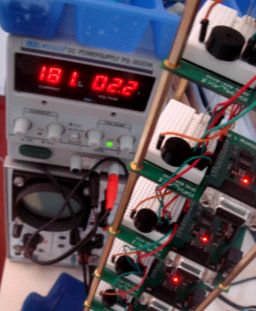
At that time, I went over to the new SEED Stamp Supercomputer and attached a Bench Power Supply with adjustable voltage. All ten processors were powered up. Starting from 9-volts, power was backed off gradually. A program was running which kept all ten piezo speakers making lots of noise. Each power LED was lit, and the stamp collective continued to perform well down to 2.2 volts. The amps draw was at elevated to 181 ma.

As the volts were backed off to 2.1, one of the boards fell off and its power LED extinguished. At 2.0, then 1.8, two more boards fell out of the collective. The experiment was repeated and this time the processors fell out at 2.0 volts. Can anyone explain Stamps working on 2 volts? I think I will build more projects from this low power Stamp board.
humanoido
Stamp SEED Supercomputer
Post Edited (humanoido) : 6/26/2009 6:58:27 AM GMT
and function properly. I first noticed the battery condition by the dim power LED. The battery was reading 1.2 volts under load.
At that time, I went over to the new SEED Stamp Supercomputer and attached a Bench Power Supply with adjustable voltage. All ten processors were powered up. Starting from 9-volts, power was backed off gradually. A program was running which kept all ten piezo speakers making lots of noise. Each power LED was lit, and the stamp collective continued to perform well down to 2.2 volts. The amps draw was at elevated to 181 ma.
As the volts were backed off to 2.1, one of the boards fell off and its power LED extinguished. At 2.0, then 1.8, two more boards fell out of the collective. The experiment was repeated and this time the processors fell out at 2.0 volts. Can anyone explain Stamps working on 2 volts? I think I will build more projects from this low power Stamp board.
humanoido
Stamp SEED Supercomputer
Post Edited (humanoido) : 6/26/2009 6:58:27 AM GMT
256 x 311 - 19K
Comments
Leon
▔▔▔▔▔▔▔▔▔▔▔▔▔▔▔▔▔▔▔▔▔▔▔▔
Amateur radio callsign: G1HSM
Suzuki SV1000S motorcycle
Post Edited (Leon) : 6/26/2009 10:12:57 AM GMT
humanoido
▔▔▔▔▔▔▔▔▔▔▔▔▔▔▔▔▔▔▔▔▔▔▔▔
Stamp SEED Supercomputer
You could have used a 1.5V AA battery!
humanoido
▔▔▔▔▔▔▔▔▔▔▔▔▔▔▔▔▔▔▔▔▔▔▔▔
Stamp SEED Supercomputer
The current PIC16C56 is rated to work down to 2.0V. Maybe Parallax left out the "brown-out" detector on the HomeWork Board. I can't find a schematic for it and I don't have one to look at.
I understand it now. I have the revision B Stamp 1 Project Board and
the latest schematic for revision C. Both schematics (rev b and rev c)
show the brownout detector.
Excerpt from the Stamp 1 Homework Board
Schematic Rev. C showing a brownout detector
on pin 4
However, as you can see in my microscope's photo, every reset pin on
every project board that I have (Rev
and no connection to pin 4 (res).
Microscope photo showing the BS1 chip with no connection on pin 4.
If you ask me, leaving off the brownout detector on the BS1 is a huge
advantage and a good judgment call by Parallax Engineers. It's likely that
circuits with 9V batteries will last far longer without it, because of the
chips rating down to a mere 2 volts.
It also opens up new possibilities for running some circuits (the piezo
speaker in this example) with a couple tiny AAA batteries. It is also
likely two watch cell batteries could power the stamp without any
5V sensor requirements.
humanoido
Post Edited (humanoido) : 6/26/2009 5:16:27 PM GMT
I actually used a discharged 1.5V cell giving about 1V, as I didn't have a suitable PS!
Leon
▔▔▔▔▔▔▔▔▔▔▔▔▔▔▔▔▔▔▔▔▔▔▔▔
Amateur radio callsign: G1HSM
Suzuki SV1000S motorcycle