

Custom Robot board in ExpressPCB
 Brandon C.
Posts: 106
Brandon C.
Posts: 106
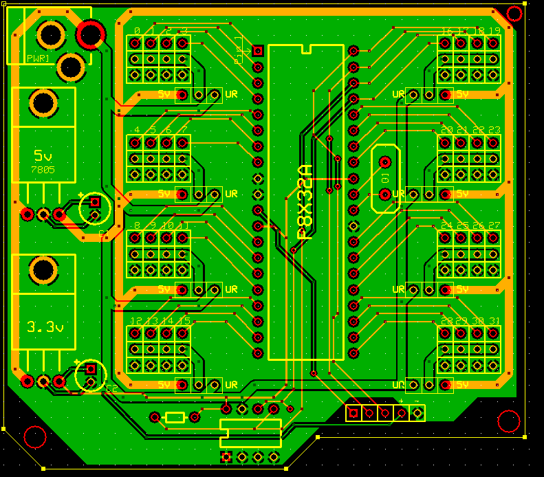
I have created a board in ExpressPCB and would like to have it made sooner or later. I'm not sure if I have all the connections correct though. could someone verify this for me, and maybe give me some suggestions for the board?
Thank you!
Brandon C.
▔▔▔▔▔▔▔▔▔▔▔▔▔▔▔▔▔▔▔▔▔▔▔▔
No purchase necessary. See back panel for more details.
Thank you!
Brandon C.
▔▔▔▔▔▔▔▔▔▔▔▔▔▔▔▔▔▔▔▔▔▔▔▔
No purchase necessary. See back panel for more details.
791 x 694 - 77K
Comments
▔▔▔▔▔▔▔▔▔▔▔▔▔▔▔▔▔▔▔▔▔▔▔▔
My Prop Info&Apps: ·http://www.rayslogic.com/propeller/propeller.htm
▔▔▔▔▔▔▔▔▔▔▔▔▔▔▔▔▔▔▔▔▔▔▔▔
--Steve
Propalyzer: Propeller PC Logic Analyzer
http://forums.parallax.com/showthread.php?p=788230
Maybe a Power Switch ?
▔▔▔▔▔▔▔▔▔▔▔▔▔▔▔▔▔▔▔▔▔▔▔▔
Brian
uController.com - home of SpinStudio - the modular Development system for the Propeller
PropNIC - Add ethernet ability to your Propeller! PropJoy - Plug in a joystick and play some games!
SD card Adapter - mass storage for the masses Audio/Video adapter add composite video and sound to your Proto Board
I'd also recommend putting some "fill" on the top-side under the regulator tabs for heat disapation - you may also want to move the regulators over so that the tab (which should be ground), isn't sitting on top of the unregulated input trace (read as "potential short after assembly")...
To reduce the possibility of brown-outs, put a stiffening cap near the servo power jumper blocks (after the +5/UR selector jumper), and you may want to make sure that your supply and +power trace can tolerate the maximum load from all simultaneous servo movements...· You only have about the same thickness on the ground "plane" as the +5V line, there is a bit of fill at the top above the +UR via, and a tiny sliver of ground below C2 where it looks like you have a dead-end bottom-side trace...
It looks like you have a dead-end trace hooked to one of the I2C lines from the EEPROM as well.
I'm also concerned about the traces to the supply caps - they look a little thin.· Remember, they need to be nice and meaty so they have a low resistance and don't act as a resistive circuit component...· On that note, use the solid via-to-fill option, you don't need to use the cross type connection - especially for power...
If power draw is not a big concern, add a status LED to the 3.3VDD/5VDD lines (as a reality check for·power supply outputs).
my $0.02...
-Tim
[noparse][[/noparse]EDIT]· I notice, if you move the servo power selector jumpers a little further away from the servo jumper blocks, you may save a servo or two from mis connection - right now you could accidentally hook up +5/UR-GND-+5 on several servos, try to offset it diagonally so that the servo cable will absolutely not fit that way.· If you are looking for a way to get more ground width, move the servo power lines that go from the selector block (center pin) to the servo connector block (entire center row) up onto the top-side.· Also, the negative leads to the caps after the v-regs don't need a separate trace, you can just tie·the pad to the fill (which you already did) and omit the trace.· This will keep from breaking up the ground plane a bit.·-T
Post Edited (GreyBox Tim) : 6/21/2009 2:44:47 AM GMT
Assuming you do the change to the servo power trace I recommended above (move to top-side), if you bring the +UR trace for the right-side servos down the right edge of your board, you will have a much better ground path for your servos on that side.· If you change your +UR trace·on the left side to simply jump from·the top selector block all the way down to the bottom (straight line), that should improve the left servo ground connection.· by running the +UR trace around the top, you'll have a nice thick ground fill around the bottom.
Also, I question the header at the bottom (for programming?)· you have a "+" line that I think you intended to run out to the +3.3VDD output of the regulator (perhaps as a programming power·input?).· I remember a datasheet many years back where if you back-fed a linear regulator it would damage it.· With a lot of capacitance behind the regulator, you may want to put a 1N4001 diode across the input/output pins, to let voltage go from the output->|-to->|-the->|-input in the event the power is disconnected or you hook-up external programming power...
-Tim
Post Edited (GreyBox Tim) : 6/21/2009 2:42:44 AM GMT
I did notice that the pin labels are not correct. and the header at the bottom is for my serial adapter.
Brandon C.
▔▔▔▔▔▔▔▔▔▔▔▔▔▔▔▔▔▔▔▔▔▔▔▔
No purchase necessary. See back panel for more details.
Leon
▔▔▔▔▔▔▔▔▔▔▔▔▔▔▔▔▔▔▔▔▔▔▔▔
Amateur radio callsign: G1HSM
Suzuki SV1000S motorcycle
The regulator pinouts are different for LM1086 or LM1117.
▔▔▔▔▔▔▔▔▔▔▔▔▔▔▔▔▔▔▔▔▔▔▔▔
Links to other interesting threads:
· Home of the MultiBladeProps: TriBladeProp, RamBlade, TwinBlade,·SixBlade, website
· Single Board Computer:·3 Propeller ICs·and a·TriBladeProp board (ZiCog Z80 Emulator)
· Prop Tools under Development or Completed (Index)
· Emulators: Micros eg Altair, and Terminals eg VT100 (Index) ZiCog (Z80), MoCog (6809)
· Search the Propeller forums (via Google)
My cruising website is: ·www.bluemagic.biz·· MultiBladeProp is: www.bluemagic.biz/cluso.htm
As to the layout, Thr Xtal could be shifted slightly towards its pins on the prop and releive some of the bunching above it. There is a servo regulator very close to the Xtal could they be shifted more into the gap between the sockets? (towards the bd edge 90 degs round and one long heatsink could be used)
▔▔▔▔▔▔▔▔▔▔▔▔▔▔▔▔▔▔▔▔▔▔▔▔
Style and grace : Nil point
I know it is not what you asked, but I have used the PRC for my yet-to-be-finished robot. it is a pretty useful layout. It might be useful to look at his layout or maintain some compatibility with his expansion boards