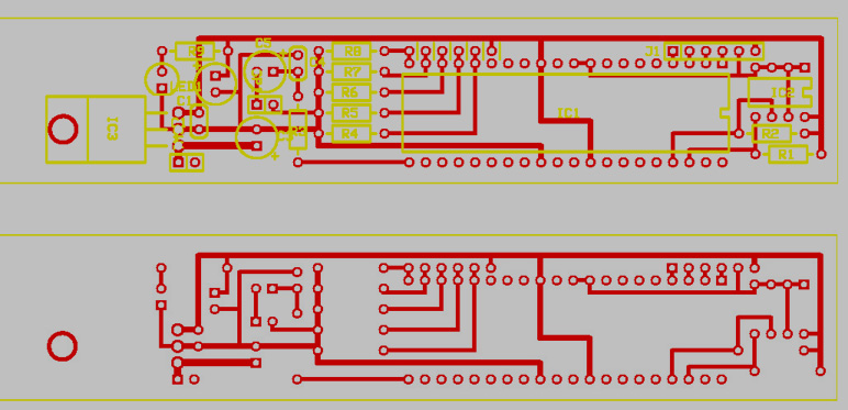
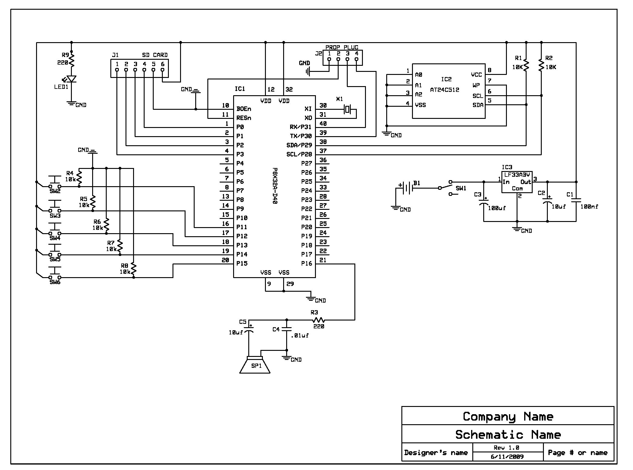
need help double checking schemetic/pcb before build.
I've been away from propellerism for a while besides that, I have never made a custom board like this before, I'd love a review from someone to make sure I'm not going to smoke my parts.
If your kids watch iCarly you may know what this is... it's a 1x1x6 in. box that has 5 buttons Each button plays a different sound, read from an SDcard. I'm going to test and see if I need an audio amp but for now it's not included.
I would also appreciate a recommendation for a small speaker. Some where in the 1W range, the amp I'll be using (if needed) will be a LM386.
I do realize there is no Propplug connection on the PCB, I'm going to program the IC on a different board.
Thanks for the help
Dave
▔▔▔▔▔▔▔▔▔▔▔▔▔▔▔▔▔▔▔▔▔▔▔▔
DGSwaner
"When in doubt, use C4" - Jamie Hyneman, Myth Buster


Comments
Just make the pcb, populate it all, and measure the current thru the + battery wire, but measure it with peak mode on, to capture the initial peak turn on spike that your circuit draws. Then do the same when you run your device thru all its possible modes, you will most likely see the peak when you playback some loud, full wave sound. Set your fuse just above your peak!
▔▔▔▔▔▔▔▔▔▔▔▔▔▔▔▔▔▔▔▔▔▔▔▔
My Prop Info&Apps: ·http://www.rayslogic.com/propeller/propeller.htm
Hes talking about your pcb file. You have two grounds that are disconnected to eachother.
What are you using to create your pcb?
you should check out www.4pcb.com and download the pcbartist program, its free and will warn you when your doing something like not connecting all 5v / GND traces to eachother.
Also, where you have "T" junctions, it's a good idea to add some diagonal copper to "fair" the traces better. In general, inside right-angle corners are bad; not fatal, though. Try to avoid right-angle turns. 45-degree turns are much better.
Once you've corrected the electrical errors, here's how to proof a PCB:
1. Print out both the layout and the schematic.
2. With a yellow overliner, trace the same circuit on both printouts, one at a time.
3. Any errors will become readily apparent, either in the course of doing this, or at the end if you have traces/circuits left over.
-Phil
The supply tracks should be a lot wider.
Leon
▔▔▔▔▔▔▔▔▔▔▔▔▔▔▔▔▔▔▔▔▔▔▔▔
Amateur radio callsign: G1HSM
Suzuki SV1000S motorcycle
I quite like the ones from CUI, available from digikey. Laptop style.
www.cui.com/catfeatures.asp?catky=638744
tubular
the caps by the regulator are there based on a schematic I found. Should I keep C2 and C3?, it's my understanding that they help compensate for power fluctuation on either side of the regulator.
I usually use a ground plane but for some reason I chose not to..... I think I will add it.
I got my schematic from the proto board pdf, I missed the bypass cap, I'll add them in.
thanks again
Dave
▔▔▔▔▔▔▔▔▔▔▔▔▔▔▔▔▔▔▔▔▔▔▔▔
DGSwaner
"When in doubt, use C4" - Jamie Hyneman, Myth Buster
-Phil
http://www.rayslogic.com/propeller/PropPCB/PCB_Boards.htm
PS:· There is a little bit of manual error checking using the route tool...
▔▔▔▔▔▔▔▔▔▔▔▔▔▔▔▔▔▔▔▔▔▔▔▔
My Prop Info&Apps: ·http://www.rayslogic.com/propeller/propeller.htm
The more decoupling caps scattered, about the better. Definately connect all VDDs and VSSs. The power to the audio amp doesn't have to be regulated and if you did try to use the 3.3v rail then there wouldn't be any drive for a LS without a bridge output stage, and the current would be high.
Leon
▔▔▔▔▔▔▔▔▔▔▔▔▔▔▔▔▔▔▔▔▔▔▔▔
Amateur radio callsign: G1HSM
Suzuki SV1000S motorcycle
Thanks for any help.
Dg
▔▔▔▔▔▔▔▔▔▔▔▔▔▔▔▔▔▔▔▔▔▔▔▔
DGSwaner
"When in doubt, use C4" - Jamie Hyneman, Myth Buster
First. You have one XTal on SCH but I cant see it on PCB.
Second. Never end traces in any other with angles only in 90 Degres.
Third. Voltage regulator is any IC and all IC's will have in standard one 100nF Decoplings Cap. Old school on Regs is that them will have 100nF on both sides of Regulator for Bypas Transcient/Parasitic high frequencies and on both sides Electrolityc/Tantalum Caps.
▔▔▔▔▔▔▔▔▔▔▔▔▔▔▔▔▔▔▔▔▔▔▔▔
Nothing is impossible, there are only different degrees of difficulty.
For every stupid question there is at least one intelligent answer.
Don't guess - ask instead.
If you don't ask you won't know.
If your gonna construct something, make it·as simple as·possible yet as versatile as posible.
Sapieha
Nick
▔▔▔▔▔▔▔▔▔▔▔▔▔▔▔▔▔▔▔▔▔▔▔▔
Never use force, just go for a bigger hammer!
The DIY Digital-Readout for mills, lathes etc.:
YADRO
2nd from my original design I did away with all 90deg corners. are you talking about. when it goes into a component. keep it at 90deg to the part...
3rd are you saying I should have a 100nf Cap on both sides of the regulator?
thanks
Dave
▔▔▔▔▔▔▔▔▔▔▔▔▔▔▔▔▔▔▔▔▔▔▔▔
DGSwaner
"When in doubt, use C4" - Jamie Hyneman, Myth Buster
On 2.
Read atached PDF document on trace building.
On 3.
Yes. Have both Types of Caps. one 100nF on both sides of Reg. and them You have in Yours schematics
▔▔▔▔▔▔▔▔▔▔▔▔▔▔▔▔▔▔▔▔▔▔▔▔
Nothing is impossible, there are only different degrees of difficulty.
For every stupid question there is at least one intelligent answer.
Don't guess - ask instead.
If you don't ask you won't know.
If your gonna construct something, make it·as simple as·possible yet as versatile as posible.
Sapieha
For a 1oz copper board low current(<500mA) signal traces can be 8mil-12mil.
Power traces for 1oz copper:
0-2A - 40mil/A
2-6A - 60mil/A
6-12 - 80mil/A
12-22 - 100mil/A
For 2oz copper divide by 2
For 3oz copper divide by 3
...
▔▔▔▔▔▔▔▔▔▔▔▔▔▔▔▔▔▔▔▔▔▔▔▔
propmod_us and propmod_1x1 are in stock. Only $30. PCB available for $5
Want to make projects and have Gadget Gangster sell them for you? propmod-us_ps_sd and propmod-1x1 are now available for use in your Gadget Gangster Projects.
Need to upload large images or movies for use in the forum. you can do so at uploader.propmodule.com for free.