

BS2 connected to Driver BLEW
 blacksheep45
Posts: 41
blacksheep45
Posts: 41
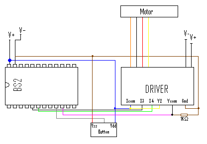
a Basic Stamp 2 connected to a ST10-Q driver chip which is connected to a stepper motor, as is shown in the diagram attached.
The Stamp is being used on a Proffesional Development Board, this is where the button is from. Also the Driver has a different power supply from the stamp as it needs 48V, 4.5A to drive the motor.
X3 and X4 are the Inputs for the Driver and Y2 is the Output From the Driver.
Can anyone help me in finding out why this circuit blew my BS2.
Kind Regards
Shaun
bmp
353K
Comments
Just made a small correction to the diagram, as I noticed that I had the Vin Pin connected up instead of the Vdd Pin. Also I numbered the Pins used so they are easier to see.
Kind Regards
Shaun
Your diagram is still hard to read. Perhaps you could separate some of the wires so it's easier to see where each one goes.
http://www.applied-motion.com/ST/
Sorry I cannot be of more use at the moment but I am just getting ready to leave work at the moment so I do not have time to make the diagram clearer but i will do this later on.
Kind Regards
Shaun
Someone else will probably point this out, but it looks like X2 is the only 5V input... X3 and X4 appear to be 12V inputs.
Without the Stamp connected to X3 and X4, can you take a voltage measurement on those two inputs with respect to GND and/or Xcom and Ycom and report those readings back to us?
▔▔▔▔▔▔▔▔▔▔▔▔▔▔▔▔▔▔▔▔▔▔▔▔
Beau Schwabe
IC Layout Engineer
Parallax, Inc.
▔▔▔▔▔▔▔▔▔▔▔▔▔▔▔▔▔▔▔▔▔▔▔▔
- Stephen
Sorry, I never noticed that I didn't attach the diagram on my second post so here it is now.
Also the readings on X3 and X4 without being connected to the stamp are:
Gnd to X3 & X4 = 0.012V
Xcom to X3 & X4 = 0.044V
Those values almost seem like a short... I would expect values of 0.6V to 0.4V for the LOW end on an input and as HIGH as Vsupply minus 0.6V to 0.4V
Can you take another measurement with a pull-up resistor of say 1K or so, and include X1 and X2?
▔▔▔▔▔▔▔▔▔▔▔▔▔▔▔▔▔▔▔▔▔▔▔▔
Beau Schwabe
IC Layout Engineer
Parallax, Inc.