

9 pin Serial Port Connecter
 5ms?
Posts: 21
5ms?
Posts: 21
Hi All,
I would like to make a universal Serial Port Connecter, with access to the 9 pins, I have the BS2, SX20, SX28, SX40 chips.
B4 you say it, I do have an SX Key & SX Blitz.
It will be mainly for the sx's, but I'll need it for programming and debugging the bs2 to.
I've drawn a circuit, I'm very new at this, will it's a start!, it's probably bad, probably needs some Capacitors, and the resistors looked at............
So Please some one!, give me some HELP!, with the schematic.
I would like to make a universal Serial Port Connecter, with access to the 9 pins, I have the BS2, SX20, SX28, SX40 chips.
B4 you say it, I do have an SX Key & SX Blitz.
It will be mainly for the sx's, but I'll need it for programming and debugging the bs2 to.
I've drawn a circuit, I'm very new at this,
will it's a start!, it's probably bad, probably needs some Capacitors, and the resistors looked at............So Please some one!, give me some HELP!, with the schematic.
464 x 706 - 42K
Comments
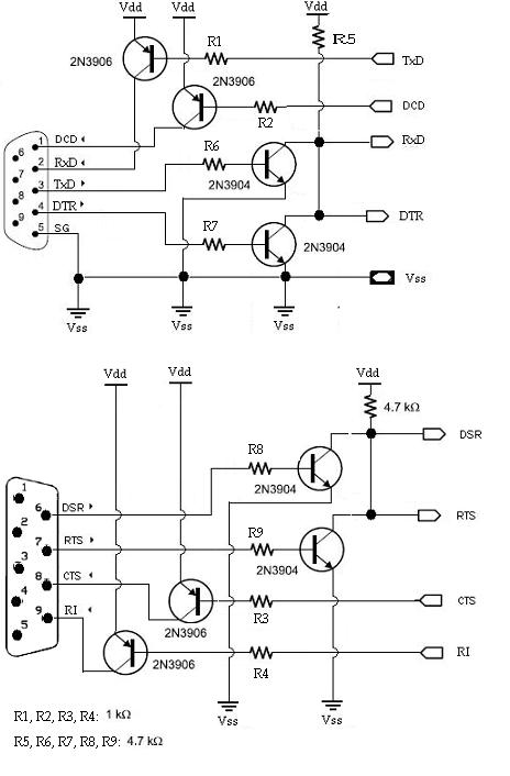
Yes, I have "BASIC Stamp 2e Interpreter Chips" and SXs Chips they don't have built in transistors like the BASIC Stamp 2 or the BS2p40-IC.
I don't have a MAX232 (or MAX3232), but have lots of 2n3904s and 2n3906s.
I have access to the RxD (Receive Data) and TxD (Transmit Data).
But would like access to the DTR (Data Terminal Ready) and DCD (Carrier Detect), DSR (Data Set Ready), RTS (Request To Send), CTS (Clear To Send), RI (Ring Indicator) as well.
{like the big boys}.
Thanks
5ms
Post Edited (5ms?) : 6/11/2009 11:24:11 PM GMT
How did you get on with your "universal Serial Port Connecter", I to, need one.
I found this Schematic
from nv153.pdf
I know nothing about electronics, so would you help me with this.
Thanks!
Lee
Leon
▔▔▔▔▔▔▔▔▔▔▔▔▔▔▔▔▔▔▔▔▔▔▔▔
Amateur radio callsign: G1HSM
Suzuki SV1000S motorcycle
Sorry, I know nothing about electronics to,
I posted here hoping for some help.
The schematic you posted looks good, the circuit might be help fill with the diode and cap.
Do you know how big is the cap?
Cheers,
5ms
Leon
▔▔▔▔▔▔▔▔▔▔▔▔▔▔▔▔▔▔▔▔▔▔▔▔
Amateur radio callsign: G1HSM
Suzuki SV1000S motorcycle
Thank you.
and volts?, maybe 24v
5ms
▔▔▔▔▔▔▔▔▔▔▔▔▔▔▔▔▔▔▔▔▔▔▔▔
-Paul
Leon
▔▔▔▔▔▔▔▔▔▔▔▔▔▔▔▔▔▔▔▔▔▔▔▔
Amateur radio callsign: G1HSM
Suzuki SV1000S motorcycle
▔▔▔▔▔▔▔▔▔▔▔▔▔▔▔▔▔▔▔▔▔▔▔▔
-Paul
Leon
▔▔▔▔▔▔▔▔▔▔▔▔▔▔▔▔▔▔▔▔▔▔▔▔
Amateur radio callsign: G1HSM
Suzuki SV1000S motorcycle
Welllll..My attempt at it.
Remember this is the blind leading the blind, and not shore if it well fry your chips or your Serial Port.
Maybe Leon, or Some one well take a look.
And remember I what to make 1 2 [noparse];)[/noparse]
Lee.