TSL1401-DB Linescan Imager in the Classroom: Tracking the Simple Pendulum
 Phil Pilgrim (PhiPi)
Posts: 23,514
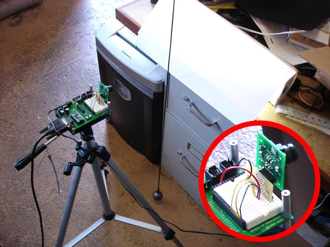
The Parallax TSL1401-DB Linescan Imager can be used to monitor kinematic experiments and demonstrations. I've set up a simple pendulum, consisting of a sixteen-ounce fishing weight, suspended from the ceiling by a black nylon cord. Using a DB-Expander, I mounted the linescan module to a BS2 Board of Education, which was then mounted on a tripod, and aimed it at the black cord. Behind the cord is one of those cheap under-cabinet fluorescent fixtures that you can get from the hardware store. Backlighting usually provides the highest optical contrast and is recommended whenever possible. (The lamp was a little too bright, so I cut down the intensity by covering it with several sheets of white paper.) Here's a photo of the setup:

You can use the BS2 program, TSL1401_scan.bs2 (downloadable from the TSL1401-DB product page) to help aim the linescan module and get the lighting right. Once that was set up, I ran the following program to track the motion of the cord back-and-forth across the field of vision as the pendulum swings:
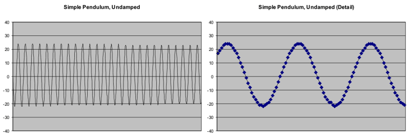
Once the program finished, I copied the data from the DEBUG screen and pasted it into an Excel spreadsheet column and created a chart. Here's how it came out:

This yields a very plain demonstration of the oscillations' non-decaying sinusoidal shape.
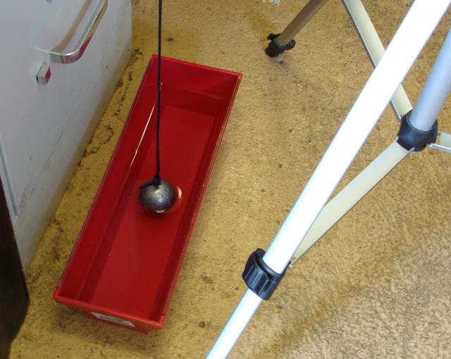
Next, I filled one of those plastic drywaller's trays from the hardware store with water, and placed it under the pendulum so about half the weight was submerged:

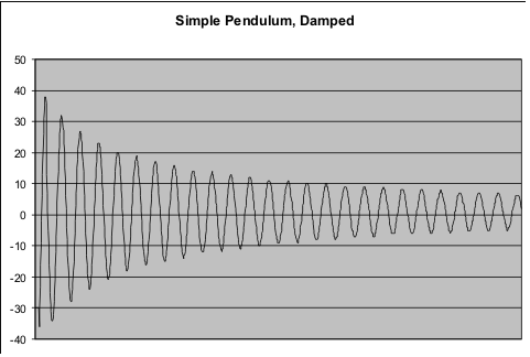
This causes viscous damping, which should show up as an expoentially-decreasing swing amplitude. Indeed, it does:

This demonstrates one application of the TSL1401-DB in the lab/classroom. It can also be used to monitor spring/mass systems, elastic and inelastic collisions, and other visible phenomena that occur in a single dimension. For monitoring faster events, the BASIC Stamp 2pe Motherboard, with its onboard coprocessor for handling the linescan chores, is recommended.
-Phil
Post Edited (Phil Pilgrim (PhiPi)) : 6/10/2009 5:30:19 AM GMT
You can use the BS2 program, TSL1401_scan.bs2 (downloadable from the TSL1401-DB product page) to help aim the linescan module and get the lighting right. Once that was set up, I ran the following program to track the motion of the cord back-and-forth across the field of vision as the pendulum swings:
' =========================================================================
'
'   File...... track_pendulum.bs2
'   Purpose... Pendulum motion tracking using the TSL1401-DB
'   Author.... Phil Pilgrim, Bueno systems, Inc.
'   E-mail....
'   Started... 9 June 2009
'   Updated...
'
'   {$STAMP BS2}
'   {$PBASIC 2.5}
'
' =========================================================================


' -----[noparse][[/noparse] Program Description ]---------------------------------------------

' This program demonstrates image capture and processing using the
' TSL1401-DB (Parallax p/n 28317). It continuously acquires and displays
' images from the TSL1401R sensor chip. After each scan, it locates the
' first dark pixel in the field of view and sends its position to the DEBUG
' screen. This can be used for tracking the positions of objects in
' kinematic experiments, such as pendulums.

' -----[noparse][[/noparse] I/O Definitions ]-------------------------------------------------

ao      PIN 0            'TSL1401R's analog output (threhsolded by Stamp).
si      PIN 1            'TSL1401R's SI pin.
clk     PIN 2            'TSL1401R's CLK pin.

' -----[noparse][[/noparse] Constants ]-------------------------------------------------------

DARK    CON 0            'Value assignd to "which" for dark pixels.
LIGHT   CON 1            'Value assigned to "which" for light pixels.
L2R     CON 0            'Value assigned to "dir" for left-to-right search.
R2L     CON 1            'Value assigned to "dir" for right-to-left search.

' -----[noparse][[/noparse] Variables ]-------------------------------------------------------

pdata   VAR Word(8)      'Pixel data, as acquired LSB first from sensor.
pixels  VAR pdata.BIT0   '128-bit pixel array mapped onto pdata.
exp     VAR Word         'Exposure (integration) time in 2uSec units.
lptr    VAR Byte         'Left pixel pointer for count and find operations.
rptr    VAR Byte         'Right pixel pointer for count and find operations.
i       VAR Byte         'General-purpose index.
cnt     VAR Word         'Sample counter.


' -----[noparse][[/noparse] Program Code ]----------------------------------------------------

' NOTE: This code assumes that DEBUG will wrap after 128 characters,
'       regardless of the DEBUG window width. Later versions of DEBUG
'       may not do this, and you will have to add CRs where needed.

exp = 8333               'Set exposure time to 8333uSec (1/120th sec).
                         'Exposure should be an integer multiple 1/2 the
                         'line frequency when illumination is by
                         'fluroescent lamps, in order to eliminate
                         'flicker.

DEBUG CLS
FOR cnt = 1 TO 1000      'Begin the scan-and-process loop (1000 samples).
  GOSUB GetPix           'Obtain a pixel scan.
  GOSUB FindPendulum     'Find the pendulum position.
  DEBUG SDEC lptr - 63, CR
  'PAUSE 50              'Uncomment to slow sample rate, if necessary.
NEXT
END

' -----[noparse][[/noparse] Subroutines ]-----------------------------------------------------

' -----[noparse][[/noparse] GetPix ]----------------------------------------------------------

' Acquire 128 thresholded pixels from sensor chip.
' exp is the exposure time in microseconds.

GetPix:

  SHIFTOUT si, clk, 0, [noparse][[/noparse]1\1]           'Clock out the SI pulse.
  PWM clk, 128, 1                      'Rapidly send 150 or so CLKs.
  PULSOUT si, exp >> 1 MIN 1016 - 1016 'Wait for remaining integration time.
  SHIFTOUT si, clk, 0, [noparse][[/noparse]1\1]           'Clock out another SI pulse.
                                       'Read 8 words (128 bits) of data.
  SHIFTIN ao, clk, LSBPRE, [noparse][[/noparse]pdata(0)\16, pdata(1)\16, pdata(2)\16, pdata(3)\16]
  SHIFTIN ao, clk, LSBPRE, [noparse][[/noparse]pdata(4)\16, pdata(5)\16, pdata(6)\16, pdata(7)\16]
  RETURN

' -----[noparse][[/noparse] FindPendulum ]----------------------------------------------------

' Locate the first dark pixel in the field of view. Subroutine is
' designed to take a constant amount of time, regardless of pendulum
' location.

FindPendulum:

  FOR i = 0 TO 7
    IF (pdata(i) <> $ffff) THEN rptr = i << 4
  NEXT
  FOR i = rptr + 15 TO rptr
    IF (pixels(i) = DARK) THEN lptr = i ELSE lptr = lptr
  NEXT
  RETURN
Once the program finished, I copied the data from the DEBUG screen and pasted it into an Excel spreadsheet column and created a chart. Here's how it came out:
This yields a very plain demonstration of the oscillations' non-decaying sinusoidal shape.
Next, I filled one of those plastic drywaller's trays from the hardware store with water, and placed it under the pendulum so about half the weight was submerged:
This causes viscous damping, which should show up as an expoentially-decreasing swing amplitude. Indeed, it does:
This demonstrates one application of the TSL1401-DB in the lab/classroom. It can also be used to monitor spring/mass systems, elastic and inelastic collisions, and other visible phenomena that occur in a single dimension. For monitoring faster events, the BASIC Stamp 2pe Motherboard, with its onboard coprocessor for handling the linescan chores, is recommended.
-Phil
Post Edited (Phil Pilgrim (PhiPi)) : 6/10/2009 5:30:19 AM GMT


Comments
- H
▔▔▔▔▔▔▔▔▔▔▔▔▔▔▔▔▔▔▔▔▔▔▔▔
No matter how much you push the envelope, it'll still be stationery.
-Phil
when you turned on the basic stamp with the camera connected to it, did the LEDs next p0, p1 flash red?!
this is happening with me and i can not figure out what does it mean
thanks
▔▔▔▔▔▔▔▔▔▔▔▔▔▔▔▔▔▔▔▔▔▔▔▔
·"If you build it, they will come."
I also noticed that Parallax is selling the Ping with the mount and servo for the same price I paid for the Ping alone. Anyone who doesn't own one should buy one pronto for that combo price! The combo makes an awesome sensor. No I don't work for Parallax, I just keep spending money on their gear.