

BASIC Stamp Activity Kit [solved]
 mzracer360
Posts: 6
mzracer360
Posts: 6
I purchased the What's a Microcontroller kit as a refurbished item off of a Parallax ebay auction. I've gone through chapters 1 - 8 just fine, and have been learning a bunch from it.
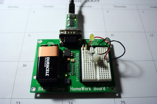
I'm now on chapter 9: Electronic Building Blocks. I've built the Transistor circuit according to Figure 9-3, but when I turn the knob of the potentiometer, nothing happens. I don't have any output from the LED. I've also tried it with the Digital Potentiometer Circuit like Figure 9-7, but still nothing.
Here is a picture of my circuit, which should be identical to Figure 9-3...
- mzracer360
Post Edited (mzracer360) : 6/8/2009 10:50:48 PM GMT
Comments
One problem that I see is that you do not any wire or wires·to the Basic· Stamp Pins
Pin # 8 need to hook up to the Bread Board
Everything else look good from what I can see
That would be a big Reason for it not to work at all
I took a look at your past post ............>>>>>>>>>
Food for thought··Just an·
One thing you need to get in a habit·is letting us know if what we have ask you try work or not
because what will happen some time down the road you may or may not get any more help from people on the Fourm
Take this as little bit of advise and nothing more ··
▔▔▔▔▔▔▔▔▔▔▔▔▔▔▔▔▔▔▔▔▔▔▔▔
··Thanks for any·
·
·
·
·
Sam
Post Edited (sam_sam_sam) : 6/8/2009 4:13:39 AM GMT
Also, about not replying back with my last topic. Even though I didn't post back on the forums, I'd been in contact with Whit via PMs, and we got everything figured out. I try to reply back to every post I make on forums, but sometimes I completely forget about a forum if I don't visit it daily.
thanks,
mzracer360
Rich H
edit - fixed, it now works!!!
Post Edited (mzracer360) : 6/8/2009 10:50:26 PM GMT