

SX28 Chip Based Handheld
 Green Phantom
Posts: 21
Green Phantom
Posts: 21
Remember when back in January 19, 2008 (1/19/2008) I posted a topic about using HCMS-29XX serial 8-digit dot-matrix LED displays for a handheld "computer?"
I had been very carefully studying the data sheets at Avago and just now, this weekend, I tested one of two of the HCMS-291X displays; one red (HCMS-2912) and one green (HCMS-2913.)· It was very tricky to program with the SX microcontroller because there were new considerations for the connections to the SX which I discovered at the 11th hour.· I couldn't simply leave the LED display's pin #15, RS, tied to ground.· After reviewing the Avago data sheets, I discovered that I was required to program the device's light intensity for both the left digits and right digits.· Just last night, I had trouble with the negative-edged RESET pin (#24) on the HCMS display device as well as for the RS pin.· When I finally got the display lighting up, there was still a problem.· Only half the display lit up!
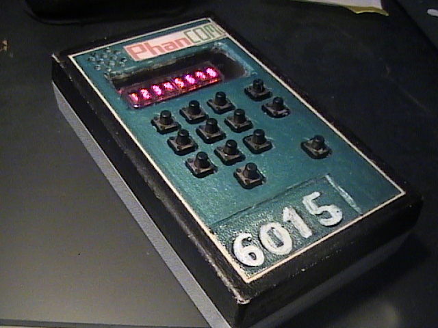
Again, nonetheless, after reviewing the manuals, I found out that out of the factory the LED displays were pre-programmed in "SLEEP" mode and I was required to edit my L6015XXX program in SX/B to shoehorn in a code to SLEEP the device and then turn on both banks of four digits of dot-matrix display.· The 2KB of ROM available in the SX28 virtually maxed out by the time I perfected the L6015 device program.· All I have left to do now is to make some final adjustments for more reliable tact switch keypad entry and I had carved out a 13-button numeric/function keyboard enclosure, one of the smaller beige project boxes from Radio Shack.
According to the data sheets, you need to enter one SLEEP instruction byte and two display brightness instruction bytes; one for the left characters, one for the right characters on the display.· You also should program the SX to send an 0 and 1 in sequence from the SX to the HCMS display RESET pin.· To initialize the display, a 1 is sent from the SX to the HCMS display pin RS (#15), followed by the three initializing instruction bytes described above.· Then RS is set to 0, where normal operation of the display is performed, to display the characters.
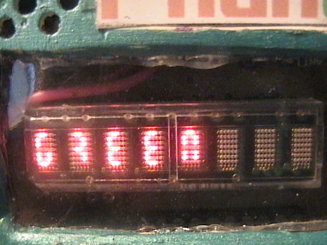
To accommodate the custom character set into the available ROM in the SX28, I had to design a unique character display font based around the 7-segment LED display.· I designed a hexadecimal-oriented ASCII character map that starts at 0 to 9 and the rest of the alpha-numeric characters and symbols start at A to Z.· I invented a programming language for the handheld device itself.· Originally I designed a 64-character custom font with readable alpha-numberic characters.· But this human-readable 64-character set requires far more work to make them readable through the display (in interpretation of hex characters and text formats)· With the "program language" in place, it wouldn't fit inside the ROM without sacrificing some of the features.· So· I took inspiration from Coleco handheld electronic football game consoles under malfunction by a bad battery and established the custom character map built around otherwise erratic symbols in a 7-segment display.· A 7-segment display can display the Greek letter mu (a backwards number 4) and I adapted it as the letter "M."· I use an upside-down "A" in 7-segment format and use it as a "W."
But I have other uses for the 64-character, human-readable, alphanumeric set.· I could make a kind of texting device with which you would send and receive, for example, a 32-character text message; a sort of TTD device as if for the deaf.
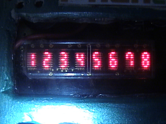
But finally, the LED display lights up!· I just took a few photos of the display in action while my little handheld, old-school computer remains under construction.
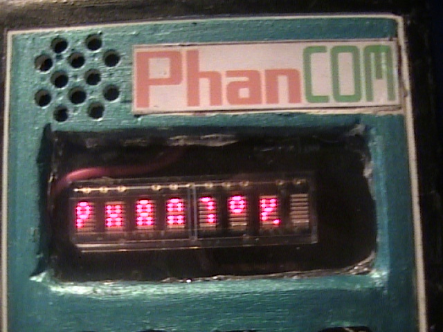
I call the device a "PhanCOM."
I hope you like it...
Green Phantom
Post Edited (Green Phantom) : 8/15/2009 9:38:14 PM GMT
I had been very carefully studying the data sheets at Avago and just now, this weekend, I tested one of two of the HCMS-291X displays; one red (HCMS-2912) and one green (HCMS-2913.)· It was very tricky to program with the SX microcontroller because there were new considerations for the connections to the SX which I discovered at the 11th hour.· I couldn't simply leave the LED display's pin #15, RS, tied to ground.· After reviewing the Avago data sheets, I discovered that I was required to program the device's light intensity for both the left digits and right digits.· Just last night, I had trouble with the negative-edged RESET pin (#24) on the HCMS display device as well as for the RS pin.· When I finally got the display lighting up, there was still a problem.· Only half the display lit up!
Again, nonetheless, after reviewing the manuals, I found out that out of the factory the LED displays were pre-programmed in "SLEEP" mode and I was required to edit my L6015XXX program in SX/B to shoehorn in a code to SLEEP the device and then turn on both banks of four digits of dot-matrix display.· The 2KB of ROM available in the SX28 virtually maxed out by the time I perfected the L6015 device program.· All I have left to do now is to make some final adjustments for more reliable tact switch keypad entry and I had carved out a 13-button numeric/function keyboard enclosure, one of the smaller beige project boxes from Radio Shack.
According to the data sheets, you need to enter one SLEEP instruction byte and two display brightness instruction bytes; one for the left characters, one for the right characters on the display.· You also should program the SX to send an 0 and 1 in sequence from the SX to the HCMS display RESET pin.· To initialize the display, a 1 is sent from the SX to the HCMS display pin RS (#15), followed by the three initializing instruction bytes described above.· Then RS is set to 0, where normal operation of the display is performed, to display the characters.
To accommodate the custom character set into the available ROM in the SX28, I had to design a unique character display font based around the 7-segment LED display.· I designed a hexadecimal-oriented ASCII character map that starts at 0 to 9 and the rest of the alpha-numeric characters and symbols start at A to Z.· I invented a programming language for the handheld device itself.· Originally I designed a 64-character custom font with readable alpha-numberic characters.· But this human-readable 64-character set requires far more work to make them readable through the display (in interpretation of hex characters and text formats)· With the "program language" in place, it wouldn't fit inside the ROM without sacrificing some of the features.· So· I took inspiration from Coleco handheld electronic football game consoles under malfunction by a bad battery and established the custom character map built around otherwise erratic symbols in a 7-segment display.· A 7-segment display can display the Greek letter mu (a backwards number 4) and I adapted it as the letter "M."· I use an upside-down "A" in 7-segment format and use it as a "W."
But I have other uses for the 64-character, human-readable, alphanumeric set.· I could make a kind of texting device with which you would send and receive, for example, a 32-character text message; a sort of TTD device as if for the deaf.
But finally, the LED display lights up!· I just took a few photos of the display in action while my little handheld, old-school computer remains under construction.
I call the device a "PhanCOM."
I hope you like it...
Green Phantom
Post Edited (Green Phantom) : 8/15/2009 9:38:14 PM GMT
640 x 480 - 121K
640 x 480 - 126K
640 x 480 - 128K
640 x 480 - 122K
Comments
I love stuff like this!
Keep at it.
cheers,
Howard
▔▔▔▔▔▔▔▔▔▔▔▔▔▔▔▔▔▔▔▔▔▔▔▔
No matter how much you push the envelope, it'll still be stationery.
Unfortunately, a few days ago, I had to redo the custom circuit board from scratch because the individual board for the LED display couldn't fit over the main board containing the SX28 microcontroller. It almost worked when I powered up the new device but the red HCMS-2912 display gave trouble, mainly due to the poor fit of the board to the enclosure. I must have accidentally bent one of the display pins and put the LEDs out of commission. So I ordered a spare display, albeit an HCMS-2972, for bigger LEDs. I am still considering desoldering the display from the board it originally was placed into and test it on the SX Tech Board. It might still be good. But I ordered the new display anyway, in case something happened.
I rebuilt the custom circuit board, now with the display and piezo speaker fully integrated with the circuit board. Just now, I ordered a 30-pin SIP wire-wrap-type circuit board component socket array which I will use to relocate the display in its new socket. The socket pins are adjusted on the board so that the display can fit behind the plastic display cutout and after soldering the SIP socket array I cut the bottom ends so the board fits in the enclosure.
The 6015 uses a 7805 regulator and is powered by a 9-volt battery. I even shoehorned in wireless communication into it! Using SERIN and SEROUT in SX/B, it sends and receives data at 2400 baud, inverted through a 433.92MHz ASK radio-frequency transmitter-receiver pair. Reason: there is no room for EEPROM circuitry to "load" programs for it. I will need to program a separate SX28 chip to contain pre-designed programs, 80 bytes each. One of the applications I propose is robotics, to send 80 bytes of data from the 6015 to a robot equipped with the RF/ASK trasmitter/recieiver modules. Other applications may include Dungeons & Dragons electronic dice rolls, chronometer, 2-way silent "texting" communication and a few games of chance.
One example of chronometer work can involve a "Hot Wheels" die-cast model car racetrack with two lanes and a digital finish line; left lane red and right lane green for LEDs and a pair of lever switches, one for each lane. When either car hits the switches, the racetrack electronic circuitry will send a signal to the 6015 which will first stop the 10-second timer on the car that made it first and then the 10-second clock for the other lane stops when the car in that other lane hits the switch, to give an example of an application.
How did you like the keypad enclosure overlay half carved out? And the grille for the piezo speaker? While the symbols in the display in one of the pictures are odd, there is a sample of the possibilities. Use your imagination!
Thanks for your reply!
Green Phantom
Neat what you can pack into such a small space, eh?
The 2400 baud radio technique sounds useful for many things.· When you get time, please tell us more about that.
Are the pair of clippers in the photo normal, fingernail sized?·· What's PhanCom's actual dimensions?
I like to take old remotes from TV's, stereo's, and VCR's and convert them into· " FrankenTrolls "·
And my first robot was made out of a cardboard shoebox [noparse][[/noparse]:=)
cheers,
Howard
▔▔▔▔▔▔▔▔▔▔▔▔▔▔▔▔▔▔▔▔▔▔▔▔
No matter how much you push the envelope, it'll still be stationery.
Green Phantom
Green Phantom