Memsic Accelerometer Running at 98 Hz instead of 100 Hz...
 grahamreitz
Posts: 56
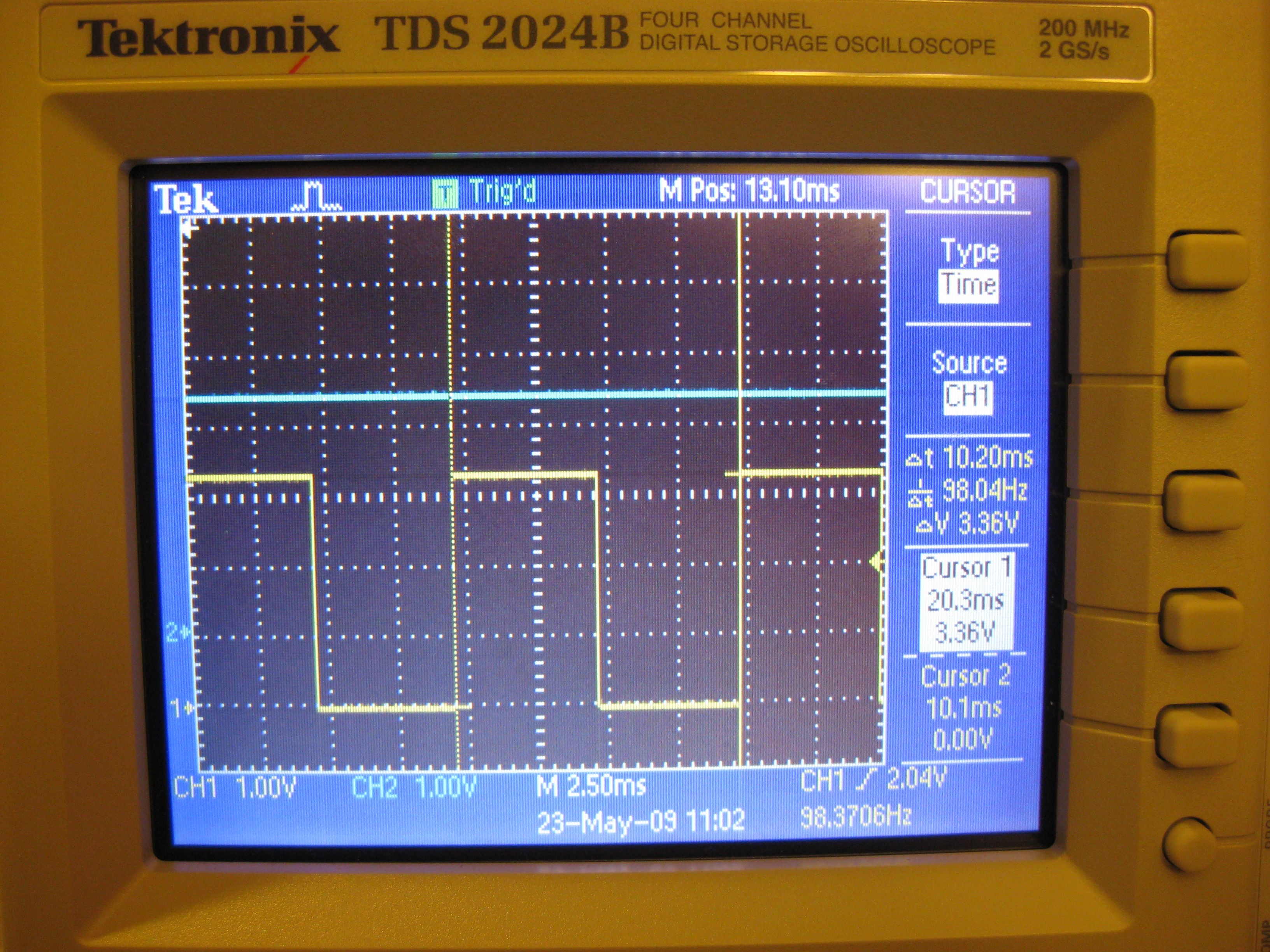
I was checking the period of the Memsic Accelerometer and noticed on the scope trace, attached (yellow trace), that it's really running at ~98 Hz, a ~10.2 ms period.
The input voltage (blue trace) is clean and at 3.3V.
Most of the conversion equations use 100 Hz as a constant.
I have two questions:
1) Is a 2% delta in the period within spec.? I might have missed it but didn't see it in the data sheet.
2) Will the 2% delta contribute much to the tilt error, when converted to degrees for angular measurements?
Thanks in advance for any advice and etc.
graham


Comments
Each axis has a 100 Hz PWM duty cycle output in which acceleration is proportional to the ratio tHx/Tx. In practice, we have found that Tx is consistent so reliable results can be achieved by measuring only the duration of tHx.
The MXD2125G&M(.pdf) datasheet indicates a Minimum frequency of 95Hz, Typical frequency of 100Hz, and a Max frequency of 105Hz.
▔▔▔▔▔▔▔▔▔▔▔▔▔▔▔▔▔▔▔▔▔▔▔▔
Beau Schwabe
IC Layout Engineer
Parallax, Inc.
Tx is definitely consistent. I think I understand why it won't matter.
If the ratio of tHx/Tx is consistent I should still get the same result regardless of the measured delta from the ideal 100 Hz (10 ms)
When at 0 degrees the duty cycle is 50% of the ideal 100 Hz (10 ms) the device should read a a ratio of 5 ms/10 ms or 0.5.
In the case when its 98 Hz (10.2 ms) the device should read a ratio of 5.1 ms/10.2 ms or 0.5. The same as above for 0 degrees @ 100 Hz.
Thanks,
graham