

Low Cost RF Circuits
 william chan
Posts: 1,326
william chan
Posts: 1,326
I have always marveled at how the chinese managed to implement very low cost RF circuits for their remote control toys, doorbells and such.
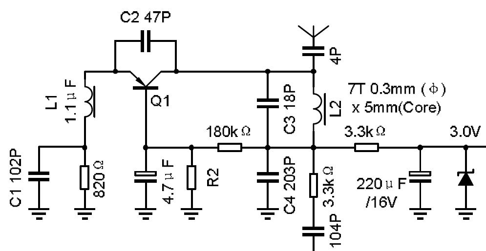
I recently stumbled on a simple RF receiver circuit.
It claims to receive signals in the 27Mhz band but is without any crystal.
Can anybody explain whether such a simple circuit would work and whether it will be stable?
See attachment.
▔▔▔▔▔▔▔▔▔▔▔▔▔▔▔▔▔▔▔▔▔▔▔▔
www.fd.com.my
www.mercedes.com.my
I recently stumbled on a simple RF receiver circuit.
It claims to receive signals in the 27Mhz band but is without any crystal.
Can anybody explain whether such a simple circuit would work and whether it will be stable?
See attachment.
▔▔▔▔▔▔▔▔▔▔▔▔▔▔▔▔▔▔▔▔▔▔▔▔
www.fd.com.my
www.mercedes.com.my
995 x 515 - 50K
Comments
Leon
▔▔▔▔▔▔▔▔▔▔▔▔▔▔▔▔▔▔▔▔▔▔▔▔
Amateur radio callsign: G1HSM
Suzuki SV1000S motorcycle
Can we use a PCB track as the receiving antenna?
How long should the track be? and should we connect both ends of the track?
▔▔▔▔▔▔▔▔▔▔▔▔▔▔▔▔▔▔▔▔▔▔▔▔
www.fd.com.my
www.mercedes.com.my
Post Edited (william chan) : 5/21/2009 10:06:26 PM GMT
A PC track can work at UHF wavelengths but would not be adequate at 27MHz.
-Phil
or try to calculate the inductance and buy a complete inductor from Farnell?
▔▔▔▔▔▔▔▔▔▔▔▔▔▔▔▔▔▔▔▔▔▔▔▔
www.fd.com.my
www.mercedes.com.my
Leon
▔▔▔▔▔▔▔▔▔▔▔▔▔▔▔▔▔▔▔▔▔▔▔▔
Amateur radio callsign: G1HSM
Suzuki SV1000S motorcycle
▔▔▔▔▔▔▔▔▔▔▔▔▔▔▔▔▔▔▔▔▔▔▔▔
Beau Schwabe
IC Layout Engineer
Parallax, Inc.
How can I add an led indicator to this circuit to light up whenever it locks on to a strong signal?
For a typical car alarm key fob that doesn't seem to use any external antennas, what frequencies do they use?
▔▔▔▔▔▔▔▔▔▔▔▔▔▔▔▔▔▔▔▔▔▔▔▔
www.fd.com.my
www.mercedes.com.my
Post Edited (william chan) : 5/23/2009 8:58:17 AM GMT
Remote controls like that used to use 433 MHz here in the UK.
Leon
▔▔▔▔▔▔▔▔▔▔▔▔▔▔▔▔▔▔▔▔▔▔▔▔
Amateur radio callsign: G1HSM
Suzuki SV1000S motorcycle