Question on the L298
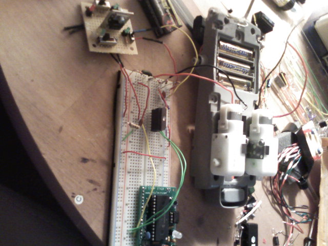
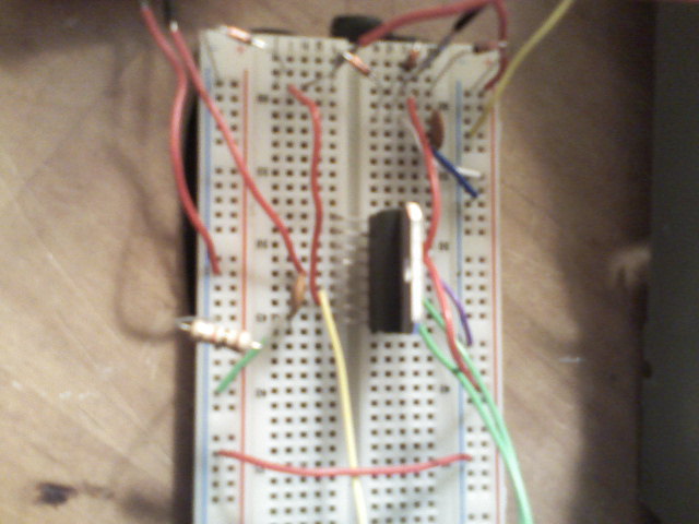
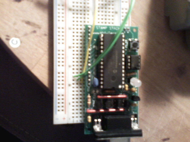
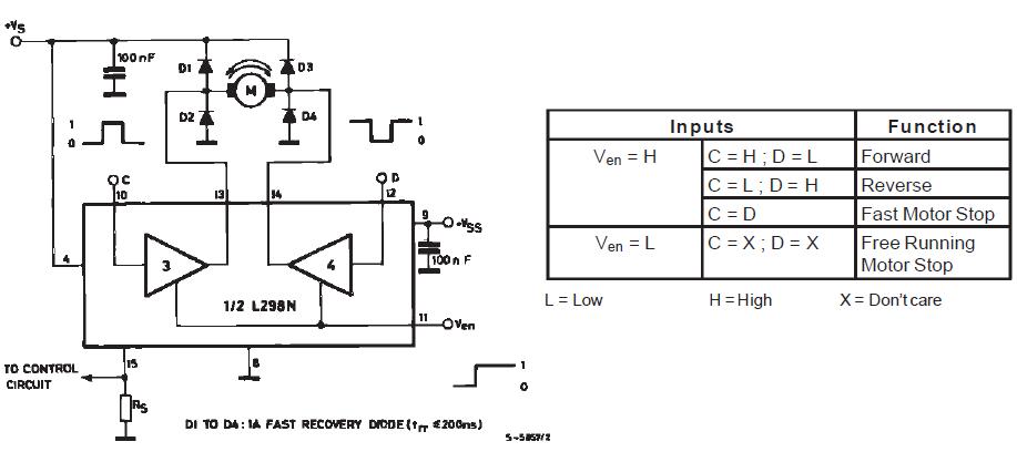
I bought a few L298's and am testing them out on a breadboard using the only schematic i could find for hooking up a motor to it (The datasheet). The schematic i am working with is below. I just had a few questions. Pin 4 = Vs and 9 = Vss, I have a breadboard voltage regulator that outputs 9 volts to the STAMP and pin 4. Then I have a switch on my VR that i can turn on another set of leads as well regulated to 5v/6v so i put 5v to pin 9 correct. I would assume this should be find because i built the VR where all negatives are common to each other. Also, I've made sure to use the extra diodes around the motor leads. My other question is about pin 15, it says on the schematic "to the control circuit" and also through a small cap to ground. I have it hooked up directly to ground because I'm not exactly sure what i'm suppose to hook this pin to (especially since the MAX voltage is about 2v i did not want to take any chances.)
Also, I'm assuming that i could use PWM to the 2 inputs but probably not to the enable right? I'm just wondering because as of now I am getting no movement from the motors.
▔▔▔▔▔▔▔▔▔▔▔▔▔▔▔▔▔▔▔▔▔▔▔▔
======
······ I'll try everything once [noparse]:)[/noparse]
Also, I'm assuming that i could use PWM to the 2 inputs but probably not to the enable right? I'm just wondering because as of now I am getting no movement from the motors.
▔▔▔▔▔▔▔▔▔▔▔▔▔▔▔▔▔▔▔▔▔▔▔▔
======
······ I'll try everything once [noparse]:)[/noparse]


Comments
Also, when using PULSOUT to the inputs my stamp restarts the program several times before the motor even spins once. I programmed in a delay of 1 second in between going one direction and another and not even that helped. Any ideas?
▔▔▔▔▔▔▔▔▔▔▔▔▔▔▔▔▔▔▔▔▔▔▔▔
======
······ I'll try everything once [noparse]:)[/noparse]
Post Edited (morris4019) : 5/14/2009 9:36:04 PM GMT
▔▔▔▔▔▔▔▔▔▔▔▔▔▔▔▔▔▔▔▔▔▔▔▔
- Stephen
▔▔▔▔▔▔▔▔▔▔▔▔▔▔▔▔▔▔▔▔▔▔▔▔
======
······ I'll try everything once [noparse]:)[/noparse]
Tim, this assume is how you were talking about sending signals to the L298?
' {$STAMP BS2}
' {$PBASIC 2.5}
' Test function of 1 motor with L289.
'
Set directions
DIRD=%0111 'Set outputs to 15 (enable), 14 (forward), 13 (reverse).
'
Constants
enable CON 15 'Enable pin 15
forDir CON 14 'Forward Direction pin 14
revDir CON 13 'Reverse Direction pin 13
speed CON 1000 'Speed constant, used in pulse to enable pin.
'
Variables
counter VAR Word ' Counter for pulsout commands.
'
Routine
'Display message.
DEBUG CR, "Running Forward..."
' First run reverse.
LOW forDir ' Use low/high to force direction.
HIGH revDir
FOR counter = 1 TO 150
PULSOUT enable, speed ' Pulse the enable pin to control speed.
NEXT
PAUSE 1000 'Delay in between pulses.
DEBUG CR, "Running Backward..."
' Next run forward.
LOW revDir ' Use low/high to force direction.
HIGH forDir
FOR counter = 1 TO 150
PULSOUT enable, speed ' Pulse the enable pin to control speed.
NEXT
OUTD=%0000 'Stop all outputs
DEBUG CR, "ending..."
END
▔▔▔▔▔▔▔▔▔▔▔▔▔▔▔▔▔▔▔▔▔▔▔▔
======
······ I'll try everything once [noparse]:)[/noparse]
▔▔▔▔▔▔▔▔▔▔▔▔▔▔▔▔▔▔▔▔▔▔▔▔
======
······ I'll try everything once [noparse]:)[/noparse]
because of the Opto-Coupler movie is to big to upload I'm attaching the youtube version of it here
' {$STAMP BS2}
' {$PBASIC 2.5}
' Motor movement for Wall-E H-Bridge using a L298N chip Test routine
' By GWJax 04 May 2008
'==============================================================================
' Set Wall-E's Varaibles
'
' Set Wall-E pin lay out
Wall_E_LfBack PIN 8 'sets left track backwards to pin 8
Wall_E_LfFront PIN 9 'sets left track foward to pin 9
Wall_E_RtBack PIN 10 'sets right track backwards to pin 10
Wall_E_RtFront PIN 11 'sets right track foward to pin 11
Wall_E_Rt_E PIN 12 'sets right motor on/off
Wall_E_Lt_E PIN 13 'sets left motor on/off
'
' setup pin I/O's
LOW Wall_E_lfBack
LOW Wall_E_LfFront
LOW Wall_E_RtBack
LOW Wall_E_RtFront
LOW Wall_E_Rt_E 'disable right motor
LOW Wall_E_Lt_E 'disable left motor
'
Main:
GOSUB Wall_E_STOP
GOSUB Wall_E_FowardFast
PAUSE 1000 ' let run for one sec.
GOSUB Wall_E_STOP
GOSUB Wall_E_BackFast
PAUSE 1000 ' let run for one sec
GOSUB Wall_E_HBStop ' opps turn off the motors!
PAUSE 500 ' pause 1/2 sec
GOSUB Wall_E_Stop ' reset lines for floating
GOSUB Wall_E_CW
PAUSE 500 ' run for 1/2 sec
GOSUB Wall_E_Stop
GOSUB Wall_E_CCW
PAUSE 500 ' run for 1/2 sec
GOSUB Wall_E_Stop
PAUSE 2000 ' wait for 2 sec
GOTO Main ' return to the main and do again
'
'Wall-E stop moving
Wall_E_STOP:
LOW Wall_E_Rt_E
LOW Wall_E_Lt_E
LOW Wall_E_lfBack
LOW Wall_E_LfFront
LOW Wall_E_RtBack
LOW Wall_E_RtFront
RETURN
'
Wall_E_FowardFast:
HIGH Wall_E_Rt_E
HIGH Wall_E_Lt_E
HIGH Wall_E_RtFront
HIGH Wall_E_LfFront
RETURN
'
Wall_E_BackFast:
HIGH Wall_E_Rt_E
HIGH Wall_E_Lt_E
HIGH Wall_E_RtBack
HIGH Wall_E_LfBack
RETURN
'
'Wall-E move clock wise
Wall_E_CW:
HIGH Wall_E_Rt_E
HIGH Wall_E_Lt_E
HIGH Wall_E_RtBack
HIGH Wall_E_LfFront
RETURN
'
'Wall-E moving counter clock wise
Wall_E_CCW:
HIGH Wall_E_Rt_E
HIGH Wall_E_Lt_E
HIGH Wall_E_LfBack
HIGH Wall_E_RtFront
RETURN
'Wall-E hard break stop
Wall_E_HBStop:
LOW Wall_E_RtBack
LOW Wall_E_RtFront
RETURN
▔▔▔▔▔▔▔▔▔▔▔▔▔▔▔▔▔▔▔▔▔▔▔▔
If a robot has a screw then it must be romoved and hacked into..
▔▔▔▔▔▔▔▔▔▔▔▔▔▔▔▔▔▔▔▔▔▔▔▔
======
······ I'll try everything once [noparse]:)[/noparse]
▔▔▔▔▔▔▔▔▔▔▔▔▔▔▔▔▔▔▔▔▔▔▔▔
======
······ I'll try everything once [noparse]:)[/noparse]
Jax
▔▔▔▔▔▔▔▔▔▔▔▔▔▔▔▔▔▔▔▔▔▔▔▔
If a robot has a screw then it must be romoved and hacked into..
Jax
▔▔▔▔▔▔▔▔▔▔▔▔▔▔▔▔▔▔▔▔▔▔▔▔
If a robot has a screw then it must be romoved and hacked into..
Running specs:
·· motors x 2 = GM9(Solarbotics)
·· voltage···· = 7.5·(5 AA)
·· motor driver = L298
I have not had a chance yet to isolate power sources 1 for each motor and stamp, but trying to get everything together to get it done within a few days. And I REALLY appretiate all the help guys. Everyone is so informative... makes learning easier, and more fun
▔▔▔▔▔▔▔▔▔▔▔▔▔▔▔▔▔▔▔▔▔▔▔▔
======
······ I'll try everything once [noparse]:)[/noparse]
▔▔▔▔▔▔▔▔▔▔▔▔▔▔▔▔▔▔▔▔▔▔▔▔
======
······ I'll try everything once [noparse]:)[/noparse]
The reason i ask is, I was looking through the 2 objects in the Obex that i found, one is "PWM Motor Driver (H Bridge)" the other "L298 PWM Motor Control". I looked through the code and I am wondering why they are both using spin and Assembly? I'm have NO knowledge of assembly language, I only use BASIC/C++/visual basic/PHP/some java/HTML/XML and now learning SPIN. In my head, after doing my research on the spin language, I thought I should be able to use PWM with a counter module, or am i wrong?
-Mike
▔▔▔▔▔▔▔▔▔▔▔▔▔▔▔▔▔▔▔▔▔▔▔▔
======
······ I'll try everything once [noparse]:)[/noparse]
Like i said before I am using a GM9 gearmotor (bought from solarbotics) and the L298 with 9v (6 AAs) output to motors. 3.3v logic input from Propeller.
To get a good picture of what i'm dealing with, with no load on a bench you can basically just hear the pulsing. But when wheels installed and under load, say making a left turn, it is very jerky from these pulses.
-Mike
▔▔▔▔▔▔▔▔▔▔▔▔▔▔▔▔▔▔▔▔▔▔▔▔
======
······ I'll try everything once [noparse]:)[/noparse]
Also how have you wired the l298 up? I use it with the pwm is going to enX pin and the inX pins are controlling the direction.
From what I could see in the picture above I dont think you have diodes on the motors - you need this or you will blow the l298.
▔▔▔▔▔▔▔▔▔▔▔▔▔▔▔▔▔▔▔▔▔▔▔▔
======
······ I'll try everything once [noparse]:)[/noparse]
Jax
▔▔▔▔▔▔▔▔▔▔▔▔▔▔▔▔▔▔▔▔▔▔▔▔
If a robot has a screw then it must be romoved and hacked into..
This is the code I use for speed control
Pub SetSpeed(Motor, Speed) | m
'' Set the speed on Motors with bit 1 to speed
'' Coasts if speed is 0
'
  repeat m from 0 to NumMotors-1
    if Motor & (|< m)                                   'for each motor command is for
      if CurrentDirection[noparse][[/noparse]m] ^ (Speed & $8000000)
        pwm.duty(PwmPin + PwmOffset[noparse][[/noparse]m], 0)              'set motor to coast if changing direction
      if (((Speed > 0) & |<m) ^ (Reverse & |<m))        'Calculate In Pins for correct direction
        outa[noparse][[/noparse]In1Pin[noparse][[/noparse]m]] := 1
        outa[noparse][[/noparse]In2Pin[noparse][[/noparse]m]] := 0
      else
        outa[noparse][[/noparse]In1Pin[noparse][[/noparse]m]] := 0
        outa[noparse][[/noparse]In2Pin[noparse][[/noparse]m]] := 1
      pwm.duty(PwmPin + PwmOffset[noparse][[/noparse]m], (||Speed)<#MAX_SPEED) 'set pwm duty cycle
      CurrentDirection[noparse][[/noparse]m] := Speed & $80000000          'Save new direction
Motor is a bitmap so you can set multiple motors. Speed is +ve for forward and -ve for back. I set the pwm to 0 when changing direction, so you dont get high currents though the motors. reverse is a bitmap of the motors which need to run reversed (i.e. forwards is backwards). So you can see I check if speed is -ve or +ve and set C and D (or In1/in2) correctly and then set the pwm duty cycle making sure I remove the -ve from the duty cycle.
-Mike
▔▔▔▔▔▔▔▔▔▔▔▔▔▔▔▔▔▔▔▔▔▔▔▔
======
······ I'll try everything once [noparse]:)[/noparse]
Morris4019, I have made an Excel spread sheet to calculate the PWM command codes and it has a D/A converter schematic for this operation. I'm working on how to show you how to use the PWM command that is designed for the BS2. As you may know the PWM command is not the same as a standard MCU PWM Command. using this spread sheet will help you find the voltages you need and what resistor and capacitor you need for the fastest refresh times. I am using this in conjunction with an Opto-Coupler circuit that will turn on/off the L298N HBridge chip with out the shudder on the motors. The Platform is almost ready and I'm working on a real simple code just to get you started with the PWM command. See attached Excel file and play around with. Just type in the yellow blocks and the spreadsheet will do the rest. Enjoy for now..
Jax
▔▔▔▔▔▔▔▔▔▔▔▔▔▔▔▔▔▔▔▔▔▔▔▔
If a robot has a screw then it must be romoved and hacked into..
-Mike
▔▔▔▔▔▔▔▔▔▔▔▔▔▔▔▔▔▔▔▔▔▔▔▔
======
······ I'll try everything once [noparse]:)[/noparse]
Sparkfun has a breakout board using the L298, the schematic is available as well.
▔▔▔▔▔▔▔▔▔▔▔▔▔▔▔▔▔▔▔▔▔▔▔▔
======
······ I'll try everything once [noparse]:)[/noparse]
▔▔▔▔▔▔▔▔▔▔▔▔▔▔▔▔▔▔▔▔▔▔▔▔
======
······ I'll try everything once [noparse]:)[/noparse]
Jax
▔▔▔▔▔▔▔▔▔▔▔▔▔▔▔▔▔▔▔▔▔▔▔▔
If a robot has a screw then it must be romoved and hacked into..
Thanks again everyone, once again you've pulled me from the bottom and helped me learn a whole lot more than what i started with. [noparse]:)[/noparse]
Also, now that i've completed the circuit for my beacons, i was wondering if anyone had any tips on ways to actually built the platform/chassis of the beacon? I was almost thinking of cutting up some round tupperware, but i was just wondering how others have done it.
-Mike
▔▔▔▔▔▔▔▔▔▔▔▔▔▔▔▔▔▔▔▔▔▔▔▔
======
······ I'll try everything once [noparse]:)[/noparse]
A bit puzzled by the duty value. I find the full range is normally usable. There is often a small range around 0 that doesn't start because the motors/gears need a bit to overcome friction. If you have mis-aligned gears this can be larger - I would check if the motors have much resistance to moving by hand.
In terms of chassis, I have used anything from foamboard with motors hot glued to it, polycarbonate, expanded pvc, aluminium, abs, a pcb board, a toy track. foamboard is a cheap, quick way to try stuff but not tough. Expanded pvc is pretty easy to use and a bit tougher. Polycarbonate/abs good but a bit harder to use. I know people who have built the chassis from wood. Lego works as well. If you dont want to spend time doing it yourself or want ideas
http://www.sparkfun.com/commerce/product_info.php?products_id=9207 for a pcb idea
http://www.pololu.com/catalog/category/26 for polycarbonate
http://www.budgetrobotics.com/shop/?cart=772317&cat=5& for expanded pvc