Sending Signals for bot-to-bot talk
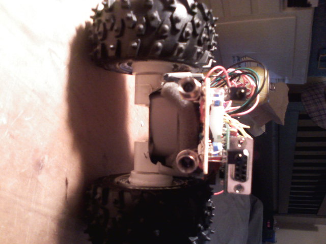
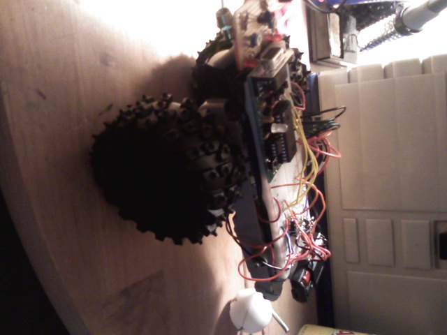
I have just finished my boe-bot-esque project, pretty much the same thing. Anyway, I have it using IR navigation and it strolls about just fine. I am having a tough time figuring out how to create a stationary beacon that will transmit a certain signal that can be picked up by my bot. The whole point is to have my bot stroll around until it senses the signal, then head toward it. Is there a way to modulate a standard IR Detector (like the ones sold as pairs at radio shack) so that it knows the difference between one signal and another?
Up to this point i have used IR as navigation, bouncing back IR light at a 38Hz detector. I understand that as the signal gets higher or lower, on this detector, than 38Hz the range drops off. I guess what i'm wondering is how to send signals back and forth, or how to tell the difference between signals.
Any help would be great. Thanks
-Mike
▔▔▔▔▔▔▔▔▔▔▔▔▔▔▔▔▔▔▔▔▔▔▔▔
======
······ I'll try everything once [noparse]:)[/noparse]


Comments
You can build a small beacon that broadcasts a given "number", say %0101. If your bot "reads" that number in the IR transmission, it sees the beacon.
But then there's a few tricky things to think about --
- direction? Which way is the beacon. An easy way to handle that is to build a long vane or tube around the detector(s) so that they have a limited angle of view. I've done some 'bots using two detectors for beacon identification with a long vane between the two. It is pretty much impossible for *both* detectors to read the number unless the bot is aimed dead on at the beacon. If it's turned to one side or the other, only one detector can pick up the number
- using the same detectors for obstacle avoidance. Can be done, but again, it gets tricky. Basically you want to check for IR reception BEFORE activating your IR leds for detection -- that way you know if what you are receiving is spurious (from the beacon) or from yourself. One way to handle the problem (you can't "listen" and "see" at the same time) is to have the 'bot stop if it picks up spurious IR and either head towards the beacon or turn around 180 so you can use the IR detectors for obstacles. Another way is to have separate detectors, but you still need to have the obstacle detectors check for IR reception before checking the 'bots own LED reflections (i.e., you wait for the detector to be high -- if it's low, then it's picking up IR from somewhere else -- then freqout the LED, then check the detector for a "hit").
Some folks make beacons that just pulse on and off -- this is fine but your 'bot will may also pick up more spurious signals (remotes, other 'bots, etc). Plus with actual numeric RX/TX you can send useful messages back and forth beyond simple beacon ID. In my own projects, I use SXes to handle continuous RX/TX of messages between 'bots and beacons since they are much cheaper than Stamps.
▔▔▔▔▔▔▔▔▔▔▔▔▔▔▔▔▔▔▔▔▔▔▔▔
When the going gets weird, the weird turn pro. -- HST
1uffakind.com/robots/povBitMapBuilder.php
1uffakind.com/robots/resistorLadder.php
-Mike
▔▔▔▔▔▔▔▔▔▔▔▔▔▔▔▔▔▔▔▔▔▔▔▔
======
······ I'll try everything once [noparse]:)[/noparse]
But that's only true if the 'bot fails to check for IR reception before doing obstacle avoidance. Then it's a question of a bit of timing and communication, for example:
check for IR detection
ir?
  no, check obstacle
  yes,
       check for start bit on (e.g.) 4 bit "message"
       start bit?
           no, check obstacle
           yes,
                get message
' now if you use 3ms start + 3 bit message, the longest TX time would be about 12ms
' so even if all that is yes, you still have time before the next servo pulse, or
' to check for an obstacle
' secondly, presume that the 'bot and the beacon both "rest" between message txes
' at least 50ms or so -- this gives plenty of quiet time

check for obstacle, 1 ms IR emitter pulse
    obstacle?
        yes, check once or twice more to be sure (loop)
        no, back to beginning

' now lets say once your bot "acquires" the beacon, you can have it SEND a
' message telling the beacon it's "listening" and the beacon could space out
' it's TXes more -- basically the 'bot can wait for the last bit of the last message
' and then "know" that it has 20 or 50 or 100ms of time to check obstacles, etc
Yes, it works, and I use something very similar, but I let a peripheral micro handle all the IR work so it's stable and easy (the host Stamp can just grab a byte that represents that last valid message received, and the sender's ID). My particular implementation actually has all the addressed 'bots/beacons/etc on a "rolling" TX rest -- each one has a different rest length, so within the space of 2 or 3 seconds, even if *all* the 'bots are TXing at once, the messages come through. I used a 12 bit message + 1 start bit, where the first (MSBFIRST) 4 bits of the message are the sender's ID, the next 4 bits are the intended recipient's ID, and the last (LSB) 4 bits are the message itself. So a 'bot searching for "home" actually sends out a message to that beacon ID asking the beacon to "turn on". The beacon then sends a continous message to the 'bot with it's own ID -- this is what the 'bot homes in on. Once it's connected to the charger, it sends a final message to the beacon telling it to shut the heck up.
However, if you want to use IR for obstacle detection and IR for RX/TX as separate units, you might want to think about using an analog IR ranger (like the Sharps) for obstacle detection and use the IR emitter/detector pair for the beacon and what not. They don't interfere with each other, especially if the ranger is aimed for floor/wall and the emitter detector are pointed out and up. Certainly on the beacon side you could just use a 556 timer set up to send out 1ms (or so) 38500hz bursts on a LED and not need a micro. Again, if you have the 1ms pulse come every 50ms, the 'bot can check for any IR detector right before pulsing it's own emitter. Even better is if it *does* see the beacon, because your program can presume at least 50ms of "dead air" immediately *following* the last pulse received.
▔▔▔▔▔▔▔▔▔▔▔▔▔▔▔▔▔▔▔▔▔▔▔▔
When the going gets weird, the weird turn pro. -- HST
1uffakind.com/robots/povBitMapBuilder.php
1uffakind.com/robots/resistorLadder.php
Post Edited (Zoot) : 5/12/2009 8:54:22 PM GMT
-Mike
▔▔▔▔▔▔▔▔▔▔▔▔▔▔▔▔▔▔▔▔▔▔▔▔
======
······ I'll try everything once [noparse]:)[/noparse]
The SX is used to make the Stamps except for the BS1 and BS2 which use PICs. It's not as easy to program the SX (or PICs) as it is to use PBasic. The Basic compiler for the SX helps a lot, but there's still a lot of detail about the SX that you have to know and use, even in Basic.
▔▔▔▔▔▔▔▔▔▔▔▔▔▔▔▔▔▔▔▔▔▔▔▔
======
······ I'll try everything once [noparse]:)[/noparse]
▔▔▔▔▔▔▔▔▔▔▔▔▔▔▔▔▔▔▔▔▔▔▔▔
When the going gets weird, the weird turn pro. -- HST
1uffakind.com/robots/povBitMapBuilder.php
1uffakind.com/robots/resistorLadder.php
▔▔▔▔▔▔▔▔▔▔▔▔▔▔▔▔▔▔▔▔▔▔▔▔
======
······ I'll try everything once [noparse]:)[/noparse]
You can probably figure out what leads are what by hooking two 1k or so resistors to gnd and +5v and apply them the leads (there would be 16 possible combination). One of those should dimly light the IR led (use a video camera with nightshot to see it, or many digital still cameras). The the other two leads are the transistor.
Obviously I'm just guessing -- there are some combined packages that feature a modulator for the IR led and then 4 leads could be +5v, GND, enable (for the emitter modulator) and signal out for the detector
▔▔▔▔▔▔▔▔▔▔▔▔▔▔▔▔▔▔▔▔▔▔▔▔
When the going gets weird, the weird turn pro. -- HST
1uffakind.com/robots/povBitMapBuilder.php
1uffakind.com/robots/resistorLadder.php
I also checked to see if all the leads where actually hooked up on the circuit board, and they are, all to different wires actually. Weird. The only reason i wanted to use them was because i am planning out my next project still and it will be very small, these emitter/detectors would be perfect because they are also very very small.
▔▔▔▔▔▔▔▔▔▔▔▔▔▔▔▔▔▔▔▔▔▔▔▔
======
······ I'll try everything once [noparse]:)[/noparse]
wheel movement... IE: If detector 1 sees the signal before detector 2, it's moving left.
This is called quadrature encoding.
The detector you've got there is most likely a set of two detectors combined together.
From what I can remember, one lead is supply, one is ground and one is for each detector.
I'm sure you can google the info fairly easily if you search for something like: ir encoder mouse
▔▔▔▔▔▔▔▔▔▔▔▔▔▔▔▔▔▔▔▔▔▔▔▔
======
······ I'll try everything once [noparse]:)[/noparse]