camera interface with pasive components
Hello together,
how can I connect a video camera to a propeller without using a fast adc?
I know that there is a microphon input on the prop demo board made only by passive components. Now I want to connect a video camera.
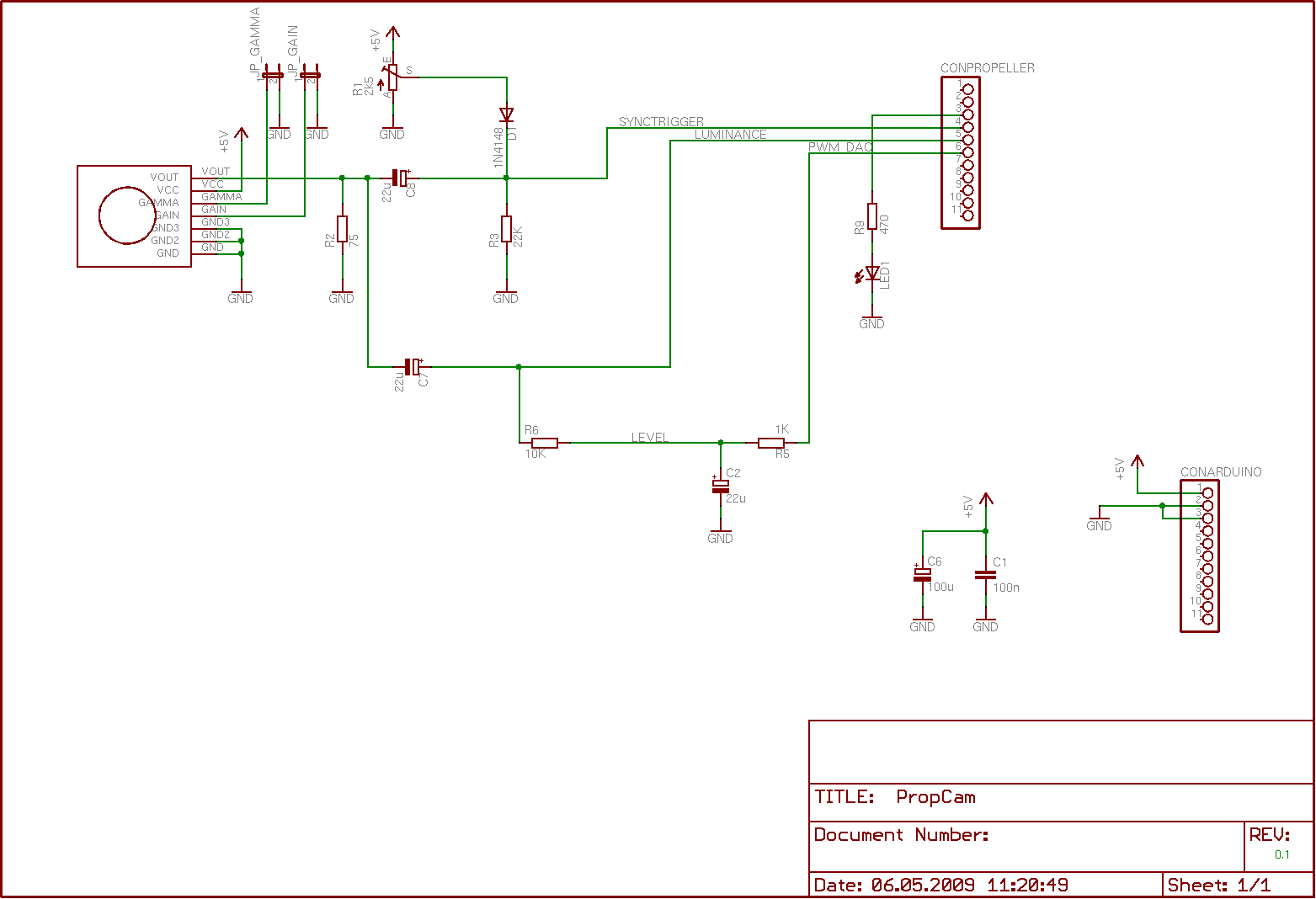
Here is my proposal for a passive camera interface realized with two digital inputs an one digital output.
1. sync signal input
2. digital dark/light input
3. pwm dac output to shift the dark/light level
What do you think about?
chris
Post Edited (Chris Micro) : 5/8/2009 8:19:52 PM GMT


Comments
http://forums.parallax.com/showthread.php?p=686552
Perry
But there is one difference: My circuit uses two digital input pins ( sync and signal ). With this setup one can achive a much higher resulution because the signal pin can be sampled much faster. The trade of is: it has only on bit resultuion ( dark and light ). But if one takes consecutive picuters and shifts the compare level in every picture one can get pictures of a still image with more bits. In my circuit the compare level for the signal can be shiftet by a digital output ( pwm dac ).
I know the lm1881. But I wanted to avoid this chip and try to realize the circuit with only passive components. My sync separator consists of the poti and a diode ( see schematic ). With this circuit it is more or less possible to detect the negativ sync pulses in the video signal.
In my experiments I could detect the line sync signals with this circuit.
-Phil
you are right: It cost a lot of time to develop such a circuit by itself. But wouldn't it be usefull for a lot of propeller users to have a minimalistic video input like the mikrofon input?
I made a minmalistic camera interface for an atmega8 .
The sync separator there is realised in the same way as propossed in the first post: the video signal is clamped with a diode to a switching level.
The Atmega8 has a specialised comparator input. The detection of the sync pulse with this input works pretty well.
With the propeller it seems to be more problematic. I don't know the excat switching levels of the imput pins and I have the impression that they shift a little bit relating to the signal history.
The analog to digtital conversion part in the LM1881 uses not much components: 2 Operational Amplifiers one with a diode Feedback to the negativ input pin ( see image attached ).
So the most components of the lm1881 are not needed by the propeller because he can to the calculation for H-Sync and V-Sync by its own.