Shop OBEX P1 Docs P2 Docs Learn Events
IR Detector Not detecting — Parallax Forums

IR Detector Not detecting

TadTad Posts: 24
edited 2009-05-02 00:23 in Propeller 1
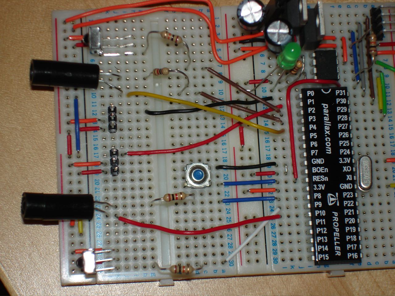
So I'm trying to put two forward looking IR Distance detectors on the front of my PE Kit. I've got 5V running down the the front of the breadboard for the IR detecters. The IRLED resisters are 1K and the detectors resistors are 10K. Attached is a picture.

I know the IRLED's are going because I can see them flashing when I use my video camera. I have attached code and a picture. Thanks in advance. I'm stumped!

Code...
CON

  _xinfreq = 5_000_000                      
  _clkmode = xtal1 | pll16x

  L = 0
  R = 1      
    CLS = 16, CRSRX = 14, CLREOL = 11  
VAR

  long servo

OBJ
  piezo     : "Piezospeaker" 
  s         : "Servos"
  ir     : "IrDetector"
  debug  : "FullDuplexSerialPlus" 

PUB init | dist

  piezo.beep(16, 2637, 2637) 

  'Variables will be monitored by servos object.  Both are initialized
  'to stop (range is -1000 to 1000 with 0 = stop).
  servo[noparse][[/noparse]L] := 0                              
  servo[noparse][[/noparse]R] := 0

  ir[noparse][[/noparse]L].init(8,10, 9)
  ir[noparse][[/noparse]R].init(3,4,2) 
  debug.Start(31, 30, 0, 57600)

   debug.tx(CLS)    
  'Pass low to high pins for a contiguous range of servos.  Left servo
  'is connected to P0, right is connected to P1
  s.start(0, 1, @servo)


  repeat
    debug.str(string(CRSRX, 11))
    dist :=ir[noparse][[/noparse]L].Distance 
    debug.dec(dist)
    dist :=ir[noparse][[/noparse]R].Distance
    debug.str(string("-"))
    debug.dec(dist) 
    waitcnt(clkfreq/3 + cnt)

Post Edited (Tad) : 5/1/2009 2:49:51 AM GMT

Comments

  • Zap-oZap-o Posts: 452
    edited 2009-05-01 01:50
    Do the receivers need to be fashioned as a Voltage divider so that the propeller can interpolate the signal?

    Please let us know if you are even getting a signal from the prop to the computer program?
  • TadTad Posts: 24
    edited 2009-05-01 01:59
    So I'm a complete newb at wiring stuff as you can see so I don't know what a voltage divider is. The program just outputs 256-256 all the time no matter how far I move my hand or whatever in front of the IRLED. If I break the circut, it goes to 0.
  • Roger LeeRoger Lee Posts: 339
    edited 2009-05-01 02:20
    Not an answer, but a comment.

    I got a scare when I looked at the photo. I ALWAYS ( most of the time) use black coated wire for ground.
    My understanding this is standard. Helps me anyway.
    That red one on BOEn just jumped out at me.

    good photo by the way.
  • Zap-oZap-o Posts: 452
    edited 2009-05-01 02:20
    Well If i knew where you got the hardware I could quickly look over the data sheets. I can say that the code looks good but, I have none of the objects that you have listed.
  • BADHABITBADHABIT Posts: 138
    edited 2009-05-01 02:26
    How does that receiver pickup distance? Doesn't it just go low when IR hits it?
  • Roger LeeRoger Lee Posts: 339
    edited 2009-05-01 02:27
    In the CON section: _clkmode = xtal1 | pll16x

    should that be _clkmode = xtal1 + pll16x

    If that changes clock speed who knows what effect on timing.

    Roger
  • Zap-oZap-o Posts: 452
    edited 2009-05-01 02:28
    I think that he is using some code to measure an analog value (a type of RC). This is why I thought that he needed a voltage divider of some kind.
  • TadTad Posts: 24
    edited 2009-05-01 02:48
    I uploaded the IRDetector and Squarewave that it uses. These come right out of the PEK.
  • Roger LeeRoger Lee Posts: 339
    edited 2009-05-01 03:24
    OK, Looks like no help so far, more rambling from me.

    You said in initial post IR Detector resistors are 10K, are they perhaps 20K. Just asking...

    Have you checked them with a meter.

    BTW: at one time the drawing in the " IR Object and Distance Detection " Lab did not match the Detector shipped with the PEK.
    ( This was PE Lab: Counters v0.8 dated 5/22/2007 ) I'm sure this has been corrected by now.

    Roger

    Post Edited (Roger Lee) : 5/1/2009 3:30:03 AM GMT
  • kwinnkwinn Posts: 8,697
    edited 2009-05-01 03:39
    A 1 K resistor sounds high for the IR led. What voltage is it running at? If it is 5V the resistor should be around 220 ohms.
  • TadTad Posts: 24
    edited 2009-05-01 04:23
    I'm red/green color blind (a fact I learned in high school electronics class since I kept blowing up projects because I never got the resistance right). At the time I wanted to be an electrical engineer but I was thus deterred since I figured I'd always be struggling with ohms. So I became a software guy instead. So this project is my big re-entry into electrical stuff 20 years hence.

    So in short, I always check every resistor with an ohm meter so I don't blow anything up.

    The IRLED's are 3.3v. Only the PNA6402 (IR Detectors) are 5v.

    I took the ohms down to 500 then to 220 on one of the LED's. No luck.
  • TadTad Posts: 24
    edited 2009-05-01 04:31
    I did however notice when the IRLED cath node is hocked back to the chip like mine does the LED is supposed to be 100 ohm. Not the 1K. Thats for when the LED goes to ground. Still not working. But brighter LEDs will help maybe.
  • BADHABITBADHABIT Posts: 138
    edited 2009-05-01 07:06
    Are you sure the leds are pulsing 38khz?
  • JonnyMacJonnyMac Posts: 9,208
    edited 2009-05-01 11:50
    I'm not sure you have your IR detectors connector correctly -- it looks to me like you've got the 5v rail and detector output pins swapped.

    I was experimenting with a simple IR pulse measurement program the other day; you might give it a try (on its own) to check your connections. If you point an IR remote at this the terminal will show you the detected pulse widths (in microseconds).
  • kwinnkwinn Posts: 8,697
    edited 2009-05-01 12:10
    Tad, you need a resistor between the led and the pin that is driving it. A 100 ohms at 3.3V (less the led forward voltage) should give about 15mA so you may want to go a bit lower...maybe 68 ohms. Posting a schematic would be a great help.
  • TadTad Posts: 24
    edited 2009-05-02 00:23
    JonnyMac gets the Christmas turkey. I had them in backwards. I noticed that the picture in the book has it bent over backwards and when I flipped it, all was well. Except now I keep getting "No Propeller Chip found" when I try to load the program. I'm going to start a new thread though with that.

    Thanks for the help!!!
Sign In or Register to comment.