

More transistor questions.
 russ christensen
Posts: 84
russ christensen
Posts: 84
Hi, i was playing around with multisim, trying to get a switch design working, and since it had a simulator i wouldn't have to constantly rewire stuff.· I am attaching a pictures of the simulator running, with what i thought should work, and wondering if anybody can explain the low voltages i'm getting out of the transistor, and why the led isn't coming on.· If i up the 3.3v in the middle to 5v, the led will come on and i get about 3.9 volts out of the transistor.· Thanks in advance.·
Russ
Russ
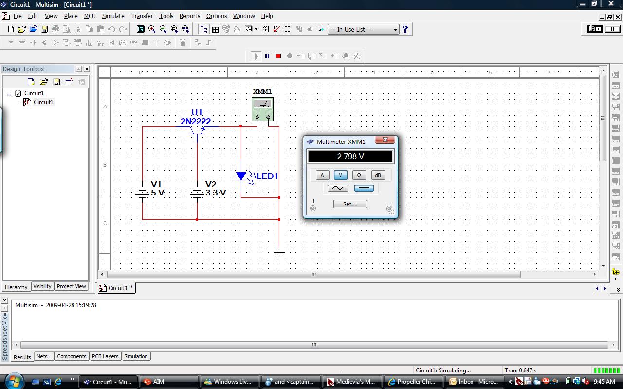
1280 x 800 - 188K
Comments
▔▔▔▔▔▔▔▔▔▔▔▔▔▔▔▔▔▔▔▔▔▔▔▔
Airspace V - international hangar flying!
www.airspace-v.com/ggadgets for tools & toys
A transistor's collector current depends on the base current (by a factor of the current gain or hFE of the transistor). Typically this gain is somewhere in the range of 20 to 200. That additional current will flow from the 5V source through the LED. Depending on how the simulator handles the LED, this extra current may increase the voltage drop across the LED which will reduce the base-emitter current which will reduce the collector current and things will stabilize at some new level. In a real-world circuit, things would have melted by now and stabilized at a zero current value.
Does this help any?
-Phil
Jerry
·····R = (Vdd - Vfwd(LED)) / i , where
i is the desired current. Start with about 10mA.
-Phil
Jerry
Russ
You could try tweaking the base resistor. There are compromises with the value of that resistor. Say you used 1 megohm, well hardly any current would flow into the base and the transistor would not turn on very much and you would get a dim led. Ditto with 100k (try it on a protoboard).
But if you go too low, eg 10 ohms, then you are wasting current. Current that flows into the base of a transistor is wasted - it flows out of the emitter. You need enough current to saturate the transistor, but any more is not needed. You can work out the current needed if you feel keen and know the gain of the transistor and the current you are switching and are happy with doing V=IR calculations. Or you can just go with ball park figures. I tend to use 2k7 when driving a small signal transistor from 5V, and I'd probably use 1k when driving from 3V. Just a habit I suppose, partly based on the fact I've got lots of those value resistors in the parts drawer.
Re some of the other questions:
Can the 2n2222 handle 1 amp. No. But there are other transistors that can, and they only cost a few cents more. Higher current ones tend to be a bit bigger, with different package styles as they are dissipating a bit more heat. If you can give us the maximum current I could suggest some. But 1A is a lot of current for a led - are you switching something else?
Yes, you will always need resistors!
What is a lightbar? Could we have a schematic, part # etc, maybe we can suggest a suitable driver circuit.
Addit: I did a quick google on the 2n2222 and bc549. I tend to use the latter - but I just noticed the gain values. hFE is the gain, and it is 520 for a BC549 but only 75 for a 2n2222. The gain is a useful number to know - essentially any current you put into the base gets multiplied by this amount and can flow from the collector to the emitter. Put in 1mA and 75mA will flow if the gain is 75. Now you can work out V=IR and allow for the 0.6V drop etc, get a feel for what sort of base resistors to use. Try putting a BC549 into the simulator. Perhaps think of the transistor as a current amplifier (which is different to how mosfets work).
For switching things on and off, you might use a transistor in saturation, ie you put a bit more current into the base than you really need and the transistor is definitely switched on. This means the voltage drop from the collector to the emitter is low, and this means the transistor dissipates little heat. The current flow is then determined by that 220R going into the led. You still need both those resistors though! If you want to adjust the brightness, you could start with 220R on the led (which sets the maxiumum current that can go through the led, and stops it burning out), and then gradually increase the base current resistor. You can then experiment with what happens when the transistor is operated as an amplifier.
You can switch 12V with a 2n2222. You can go up to 60V if you like, though that would be asking for trouble when a short happens. But say you use 12V. Well, you might drop 10V in a resistor to drive a 2V led. That is very wasteful. But you could put 4 leds in series, drop 8V across the leds and only 4V on the resistor. Now you get 4 times the brightness for the same energy consumption. The energy is going into the leds, not the dropping resistor. If you are driving lots of leds, use a power supply that is just a bit more than the highest voltage drop on a led. Let's say you might use a 4V supply. You can now use a switch mode supply and convert 12V to 4V with 90% efficiency, then use the 4V to run all the leds (philldapill used 5V, and you could use 5V too). This might be the most efficient way of running lots of leds. And if they are all red leds, you might drop that 4V down to 2.8V or something.
Post Edited (Dr_Acula (James Moxham)) : 4/30/2009 3:52:46 AM GMT
As a follow up question ... is it possible to use a Darlington (eg TIP120) in a non-saturated mode just by limiting the base current? If I understand correctly the true hFE is highly variable between parts ... how do you properly control the current gain in such a current amplifier circuit? I am guessing the answer is feedback, but can you point me to a description of how it is done?
I never understood Horowitz's 'Transistor Man' either ...
Cheers!
Paul Rowntree