

[PROJ] Scanner 3D
 JeanD
Posts: 15
JeanD
Posts: 15
Hello everyone ! 
I'm Jean, a french student (well, I'm in my last year of high-school). I've been messing around with a BS2 this year in a school project (I can make a topic about it if someone is interested)
For two weeks now, I've been working on a top-secret project (Ooh :0). I think that I've got a neat idea, but I think sharing it with others would be enriching, plus I think that I'll have some problems so I'll probably need some help from you guys [noparse]:p[/noparse].
Codename : S3D
The·goal of this project·is to create a machine that can scan it's surrounding to create a point cloud, viewable in 3D on a computer.
After some search it seems that this kind of machine exists, but are quite expensive (starting at 100,000$).
So, my objective is to make such a machine but with a very low budget (under 1000$). Of course, mine won't be as performant as commerical ones, I aim at a cloud point of about 100,000 points and a maximum scanning range of 10 meters. Enough for indoor environnements
Theory and Principle
The scanner is composed of 3 main elements :
The rotation of the head is driven by the microcontroller, which, at the same time, get the distance from the laser sensor.
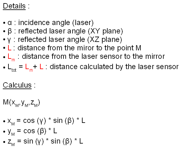
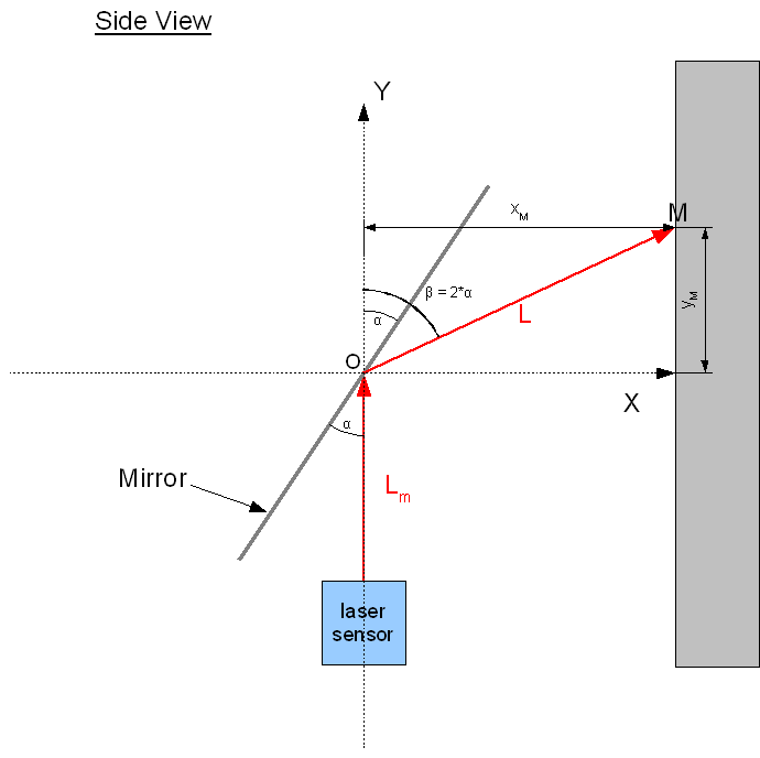
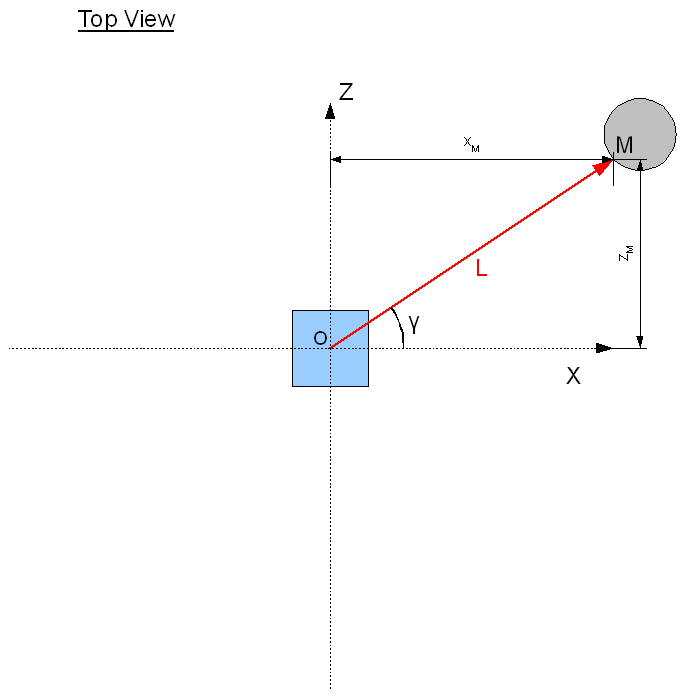
So, for each position of the rotative head, we can get a single point of the space. This is achieved with trigonometry and three values physical values :
Since I don't know how to do a schema in 3D, there are two schemas, from the front and from the side.
That's all for the moment. The project is more advanced but all I have written at the moment is in french, so I need time to translate everything.
To summerize what I've done so far·:
And here's what I need to explore :
I hope my english is not too bad !
Feel free to post.
I'll try to update soon the topic with more material.
I'm Jean, a french student (well, I'm in my last year of high-school). I've been messing around with a BS2 this year in a school project (I can make a topic about it if someone is interested)
For two weeks now, I've been working on a top-secret project (Ooh :0). I think that I've got a neat idea, but I think sharing it with others would be enriching, plus I think that I'll have some problems so I'll probably need some help from you guys [noparse]:p[/noparse].
Codename : S3D
The·goal of this project·is to create a machine that can scan it's surrounding to create a point cloud, viewable in 3D on a computer.
After some search it seems that this kind of machine exists, but are quite expensive (starting at 100,000$).
So, my objective is to make such a machine but with a very low budget (under 1000$). Of course, mine won't be as performant as commerical ones, I aim at a cloud point of about 100,000 points and a maximum scanning range of 10 meters. Enough for indoor environnements
Theory and Principle
The scanner is composed of 3 main elements :
- A laser distance sensor
- A miror mounted on a rotative head (two axes of rotation)
- The "brain" ( a microcontroller connected to a PC )
The rotation of the head is driven by the microcontroller, which, at the same time, get the distance from the laser sensor.
So, for each position of the rotative head, we can get a single point of the space. This is achieved with trigonometry and three values physical values :
- The distance from the mirror to the obstacle
- The angle of the laser ray in XY
- The angle of the ray in YZ
Since I don't know how to do a schema in 3D, there are two schemas, from the front and from the side.
That's all for the moment. The project is more advanced but all I have written at the moment is in french, so I need time to translate everything.
To summerize what I've done so far·:
- A basic solid works model of the machine
- Searches on effectors to use (I need precision !)
- Which sensor to use and how to send distance datas to the microcontroller (The IFM ref. O1D100 seems like a small and affordable sensor to me, yet efficient. It outputs an analog signal, proportionnal to the distance it detects, so I suppose a A to D chip like the MCP3001 would fit.)
And here's what I need to explore :
- Can a BS chip calculate trigonometry ?
- How can I store point coordinates on the PC that the BS send through serial or USB ?
- How to open and view the point database in a 3D software ? Which format should I use ?
- What type of servos would be precise, fast and yet affordable ?
- How to contrôle these precisely from the BS ?
- What would be the best mecanical solution for the rotative head ? It needs to be rather simple and yet precise (At most a precision of one degree, 0.5 degree would be great)
I hope my english is not too bad !
Feel free to post.
I'll try to update soon the topic with more material.
Comments
My first thought was to use servos.
But, it seems that these are not precise enough for my needs.
Since the movement of the rotative head is continuous, for both axes, I think that two stepper motors with a reductor would work great.
What about this kind of product : www.skfequipements.skf.fr/datasheet.aspx?lang=en&cou=2&pid=448687&cat=2126 ?
Each step is 7,5°, and with a reduction of 20, the output is really precise, one step is 0.375° on the output ! Considering that the scan is on 360° around Y, I can exactly get 960 points maximum.
And, considering that the mirror can only rotate on 160 degrees, it makes a resolution of 0.75°, that's about 213 points.
So, with the precision brought by such an effector, I can get 204 480 points, which is really enough.
I think that it won't be too hard to control these motors from the Basic Stamp, but if you got any links on the subject they are welcome !
This also brings another problem, 200 000 points is a lot, so I need to make the rotative head as fast as possible, and yet precise.
Considering that the laser sensor runs a 50Hz, I think that aiming that a frequency of 25Hz for the process of acquiring point datas is fair.
To get the whole cloud, 204 480 points, that would last 2 hours and 30 minuts. Hence we can drastically reduce this time by lower the resolution of point cloud.
I've also been looking for someway to bring my point datas from the BS to the PC.
Can I do that with Stamp Plot ? (I've never used this software, only the Stamp Editor actually).
And I'm still not sure about when and where should be done the calculus, since the BS doesn't support decimal numbers and tough trigonometry, I think that sending raw datas for each points to the PC is a better solution. Then the PC will be able to calculate all the coordinates.
Comments would be greatly appreciated ! [noparse]:D[/noparse]
If I get to work PLX-DAQ correctly, then everything is alright, I can treat all the informations easily in Excel to get my coordinates. Plus, it is quite easy to convert these coordinates from excel to the ".obj" format, which can be read by most of the 3D softwares.
The only things that worries me is the Speed to draw the datas from the BS, won't be long, or it would really slow down the scanning.
Anyway, even if it would be long, it would work, that is the most important right now.
Now, I have some questions considering my laser sensor. This sensor outputs an analog signal, ranging from 0V to 10V. The signal is strictly proportional to the distance it detects (0 to 10 meters). So I have to find a way to convert this Analog signal in a Digital signal, which could be read by the BS.
I found a tutorial on instructables.com, which explains how to do such a thing using an A to D chip (a MCP3001).
link : www.instructables.com/id/Digital-Voltmeter/
Sounds convenient, really fast (100ksps !), though not really precise : the MCP3001 has a precision of 10 bits, which is cleary not enough considering that the laser sensor has a range of 10m and has a precision of about 2 millimeters. And with 10 bits I would just be able to get a precison of 10cm, quite frustrating...
And those kind of chips doesn't go higher than 13bits (the MCP3301). That's a resolution of 8000, do you think I can manage to have a decent precision ? 1 mm equals 1 mV...
Since ths BS can't store variables of more than a Word, I'll have to go for a centimetric resolution, which remains decent .
It seems that there are other kinds of A to D chips, but then, even if they can store larger values, they have really low sample rates (4 to 15sps).
Do you have a solution to this problem ?
Message Edité (JeanD) : 4/21/2009 8:22:53 PM GMT
Anyway, what is great with the BS is that there are a lot of resources on the web.
I found some articles to know how to drive stepper motors with a BS, not that hard.
Same for the A to D converter, I've found some interessant tutorials. Though I'll have to stick to a 13 bits AtoD converter.
Still, it's a resolution of 1,2 mV, that is enough...
Oh, and I've made a flow chart that details the whole program (I've just replaced some part with some GOSUB, because the flow chart would have been too big and hard to read. The file is attached to this post.
And please guys, let me know what you think of it. Only 2 replies and almost 80 views ! Am I asking foolish questions ?
edit :
I forgot to detail two variables on my flowchart :
st_pos_h : Used to know if the head is in initial position (st_pos_h = 1 means that it's in position 0° in horizontal)
st_pos_v : Used to know if the head is in initial position (st_pos_v = 1 means that it's in position 0° in vertical)
Message Edité (JeanD) : 4/24/2009 8:58:01 AM GMT
Hi JeanD, I think you are off by a factor of 10.
10 meters = 10,000 mm right?
10,000 mm divided by 2 mm resolution = 5,000 steps no?
13 bits = 8,192 steps.
Am I missing something? It seems like a 13 bit ADC is a good fit.
Even the 10 bit ADC will give you centimeter resolution at 1,024 steps. 10 meters = 1,000 centimeters.
Interesting project, keep us posted!
Rich H
Post Edited (W9GFO) : 4/24/2009 5:45:26 PM GMT
But then, I realized that with 13 bits I would get a nice precision :
I really want to get on the BS2 and buy those parts, but I've got two wait, I own no BS2, I use the ones we use at school. Plus I've got two weeks of mock exams starting this monday.
Anyway, it's positive, it forces me to think and organize the project instead rushing to the soldering iron
I'll try to get some funding from my school, since some parts are quite expensive (the laser sensor and the stepper motors mainly).
By the way, do any of you know a good laser sensor ? My searches lead me to the IFP efector pmd (O1D00), which is compact and not too expensive, but it outputs an analogue signal. A sensor with a serial outpout would be neat, but most of them are big and very, very expensive.
Still, I found some time to work on the project.
I have worked on the steppers, and I think this part is almost finished.
Here is a simulation I made in ISIS : www.youtube.com/watch?v=nPlBQN9Lhho . That's what we use at school and it's sweet since it can simulate BASIC Stamp chips !
The video shows a stepper motor driven by a BS2. It is using half-stepping. The BS2 should be connected to a SN754410 but this chip doesn't exist in the ISIS library (Is there a way to add it to the library ?). It should be wired using this scheme :
A1,A2 and B1,B2 being the wires to the motor.
So in the simulation the motor is directly connected to the BS2, but it's supposed to work the same If I add the SN754410 using the scheme up there.
Here is the program used to drive the motor, what I need to do now, is to modify it to be used and called as a sub program in my big main program. This programm is made in a way that you can precisely go one half-step forward or one half-step backward at a time. To do that, I'm keeping the half-step position in a variable, so when it needs to kgo back and forth, it knows wich "step" to activate. I hope my english is not too bad so you can understand
[code]
' {$STAMP BS2}
' Programme de commande d'un moteur pas
As you know, I have to measure a voltage value ranging from 0V to 10V.
For this I'll be using a MCP3301.
I've been trying to simulate the thing on ISIS but it doesn't work (and I'm using the MCP3001, cause I don't have the MCP3301 in my ISIS's library, but it works ablsolutely the same way).
The problem comes after the two clock cycles of initialization and the null bit is sent, when the SHIFTIN function should be called.
In fact, it doesn't send any serial word, like it should, it just seem to skip the SHIFTIN function.
Here is the scheme in ISIS :
And here is a zoom on the logical states when it comes to the shift in function is suppose, the clock is crazy. Do you know what can be wrong ?
And here is the code I did, based on jasonbabcock’s code :
' {$STAMP BS2} ' MCP3301 to BS2 program – Scanner 3D project (program based on jasonbabcock’s one) cs CON 0 'chip select is pin 0 clk CON 1 'clock is pin 1 dat CON 2 'dat is pin 2 'make sure there is a pull-up resistor (10k) on the data pin refv CON 5 'reference voltage refvbin CON 8192 'the max value for 13 bits pt CON 1 value VAR Word 'the reading results is stored here voltage VAR Nib 'the calculated voltage is here value = 0 HIGH cs 'chip not selected HIGH clk 'clock is high INPUT dat 'dat is on input PAUSE 250 falseread: 'the first reading is always a false reading, this step ignores it LOW cs 'select that chip 'idle clock cycle 1, two are needed LOW clk PAUSE pt HIGH clk PAUSE pt 'idle cycle 2 LOW clk PAUSE pt HIGH clk PAUSE pt 'end idle clock cycles, start null bit LOW clk PAUSE pt HIGH clk PAUSE pt 'end null bit 'start shift in SHIFTIN dat, clk, MSBPOST, [noparse][[/noparse]value] 'shift in serial data 'dat and clk pin are defined 'msb means most significant bit 'msbpost means read bit after clock cycle 'the 13 bit data is stored into "value" HIGH cs 'unselect chip PAUSE 250 GOTO measure: measure: LOW cs 'select that chip 'idle clock cycle 1, two are needed LOW clk PAUSE pt HIGH clk PAUSE pt 'idle cycle 2 LOW clk PAUSE pt HIGH clk PAUSE pt 'end idle clock cycles, start null bit LOW clk PAUSE pt HIGH clk PAUSE pt 'end null bit 'start shift in SHIFTIN dat, clk, MSBPOST, [noparse][[/noparse]value] 'shift in serial data 'dat and clk pin are defined 'msbpost means read bit after clock cycle 'the 13 bit data is stored into "value" HIGH cs 'unselect chip voltage = (value / 8192) * refv * 2 'this is supposed to calculate voltage 'debug will display the value on your computer screen DEBUG HOME DEBUG "Binary Read: " DEBUG BIN value DEBUG " ", CR DEBUG "Decimal Read: " DEBUG DEC value DEBUG " ", CR DEBUG "Voltage: " DEBUG DEC voltage, CR 'this is rounded down PAUSE 10 'loop delay value = 0 'resets the value variable voltage = 0 'resets the voltage variable GOTO measure 'repeatwww.youtube.com/watch?v=YCz-q3BGsh4
And here is the code of my main programm, the sub-programm supposed to get the data from the MCP3301 has been removed, replace by a PAUSE. Don't worry if you see some french, I write all the important comments in english.
' {$STAMP BS2} ' Programme de scan complet ' Projet Scanner 3D - 2009 - Jean Dellac '************************************************************** 'Variable for PLX-DAQ X VAR Byte 'Variable to represent data sPin CON 16 'Serial Pin - P16, Programming port Baud CON 84 'Baud mode for a rate of 9600, 8-N-1 'BS2P, BS2SX use 240 for 9600, 8-N-1 'Row VAR Nib 'Variable to hold row data ' Useless '************************************************************** '************************************************************** 'Variables SCANNER 3D - Jean Dellac stepcount_h VAR Word 'total step_h count stepcount_v VAR Word 'total step_v count c_step_h VAR Byte 'step_h order, from pos 1 to 8 c_step_v VAR Byte 'step_v order, from pos 1 to 8 laser_sensor VAR Word i VAR Byte 'used for FOR TO NEXT rotation VAR Bit 'used to know rotation "sense" scan_done VAR Bit 'used to check scan completion status st_pos_h VAR Bit ' st_pose_h = 1 means 0deg position st_pos_v VAR Bit ' st_pose_v = 1 means 0deg position bp_st_pos_h VAR Byte ' used to detect physical 0 deg position bp_st_pos_v VAR Byte ' used to detect physical 0 deg position '************************************************************** 'INIT serial connection with PLX-DAQ PAUSE 1000 'Allow data communications to stabilize SEROUT sPin,Baud,[noparse][[/noparse]CR] 'Send a lone CR to ensure PLX-DAQ buffer is ready 'Label 3 columns with stepcount_h, stepcount_v, and laser_sensor SEROUT sPin,Baud,[noparse][[/noparse]CR,"LABEL,Time,Timer,stepcount_h,stepcount_v,laser_sensor",CR] SEROUT sPin,Baud,[noparse][[/noparse]"CLEARDATA",CR] 'Clear all data columns (A-J) in Excel SEROUT sPin,Baud,[noparse][[/noparse]"RESETTIMER",CR] 'Reset Timer to 0 'INIT serial connection with PLX-DAQ 'INIT STEP MOTORS STATE c_step_h = 1 c_step_v = 1 LOW 4 'all outputs put to low LOW 5 LOW 6 LOW 7 'INIT STEP MOTORS STATE 'init var scan_done = 0 'init var 'test laser_sensor = 3 'test init: 'puts the rotative head into 0deg position init_h: GOSUB stepbackward_h BUTTON 14,1,254,50,bp_st_pos_h,1,stepcount_h_init loop_init_h: PAUSE 20 GOTO init_h stepcount_h_init: stepcount_h = 0 PAUSE 500 init_v: IF st_pos_v = 1 THEN stepcount_v_init GOSUB stepbackward_v BUTTON 15,1,254,50,bp_st_pos_v,1,stepcount_v_init loop_init_v: PAUSE 20 GOTO init_v stepcount_v_init: stepcount_v = 0 PAUSE 500 IF scan_done = 1 THEN finished GOTO scan_start scan_start: rotation = 1 FOR i = 0 TO 9 PAUSE 40 GOSUB stepforward_v NEXT GOTO scan scan: GOSUB get_laser_sensor GOSUB send_data IF rotation = 1 THEN step_r1 IF rotation = 0 THEN step_r0 step_r1: GOSUB stepforward_h GOTO step_check_r1 step_r0: GOSUB stepbackward_h GOTO step_check_r0 step_check_r1 IF stepcount_h = 360 THEN change_rotation GOTO scan step_check_r0 IF stepcount_h = 0 THEN change_rotation GOTO scan change_rotation: GOSUB get_laser_sensor GOSUB send_data IF rotation = 1 THEN rotation_to_0 IF rotation = 0 THEN rotation_to_1 rotation_to_0: rotation = 0 GOTO step_v rotation_to_1: rotation = 1 GOTO step_v step_v: PAUSE 20 GOSUB stepforward_v IF stepcount_v = 170 THEN scan_end GOTO scan scan_end: GOSUB send_data scan_done = 1 GOTO init 'bounces back to init, puts the head in 0 deg position, then end the program 'SEND DATA SUB PROGRAM send_data: SEROUT sPin,Baud,[noparse][[/noparse]"DATA,TIME,TIMER,", DEC stepcount_h, ",", DEC stepcount_v, ",", DEC laser_sensor, ",",CR] RETURN 'SEND DATA SUB PROGRAM 'Get laser DATA program get_laser_sensor: 'Supposed to get the laser sensor value loaded in the laser_sensor variable PAUSE 40 'pause needed due to the sample rate of the laser sensor 'program needs to be finished !!!!!!!!!!!!!!! RETURN 'Get laser DATA program 'STEP MOTORS SUB-PROGRAMS START stepforward_h: 'one step_h forward PAUSE 1 'step delay stepcount_h = stepcount_h + 1 IF c_step_h = 1 THEN step_h_2 'checks which step to activate IF c_step_h = 2 THEN step_h_3 IF c_step_h = 3 THEN step_h_4 IF c_step_h = 4 THEN step_h_5 IF c_step_h = 5 THEN step_h_6 IF c_step_h = 6 THEN step_h_7 IF c_step_h = 7 THEN step_h_8 IF c_step_h = 8 THEN step_h_1 stepbackward_h: 'one step_h backward PAUSE 1 'step delay stepcount_h = stepcount_h - 1 IF c_step_h = 1 THEN step_h_8 'checks which step_h to activate IF c_step_h = 2 THEN step_h_1 IF c_step_h = 3 THEN step_h_2 IF c_step_h = 4 THEN step_h_3 IF c_step_h = 5 THEN step_h_4 IF c_step_h = 6 THEN step_h_5 IF c_step_h = 7 THEN step_h_6 IF c_step_h = 8 THEN step_h_7 'step_h (steps) step_h_1: LOW 4 LOW 5 LOW 7 HIGH 6 c_step_h = 1 RETURN step_h_2: LOW 5 LOW 7 HIGH 4 HIGH 6 c_step_h = 2 RETURN step_h_3: LOW 5 LOW 6 LOW 7 HIGH 4 c_step_h = 3 RETURN step_h_4: LOW 5 LOW 6 HIGH 4 HIGH 7 c_step_h = 4 RETURN step_h_5: LOW 4 LOW 5 LOW 6 HIGH 7 c_step_h = 5 RETURN step_h_6: LOW 4 LOW 6 HIGH 5 HIGH 7 c_step_h = 6 RETURN step_h_7: LOW 4 LOW 6 LOW 7 HIGH 5 c_step_h = 7 RETURN step_h_8: LOW 4 LOW 7 HIGH 5 HIGH 6 c_step_h = 8 RETURN '------------------------------ stepforward_v: 'one step_v forward PAUSE 1 'step delay stepcount_v = stepcount_v + 1 IF c_step_v = 1 THEN step_v_2 'checks which step to activate IF c_step_v = 2 THEN step_v_3 IF c_step_v = 3 THEN step_v_4 IF c_step_v = 4 THEN step_v_5 IF c_step_v = 5 THEN step_v_6 IF c_step_v = 6 THEN step_v_7 IF c_step_v = 7 THEN step_v_8 IF c_step_v = 8 THEN step_v_1 stepbackward_v: 'one step_h backward PAUSE 1 'step delay stepcount_v = stepcount_v - 1 IF c_step_v = 1 THEN step_v_8 'checks which step_v to activate IF c_step_v = 2 THEN step_v_1 IF c_step_v = 3 THEN step_v_2 IF c_step_v = 4 THEN step_v_3 IF c_step_v = 5 THEN step_v_4 IF c_step_v = 6 THEN step_v_5 IF c_step_v = 7 THEN step_v_6 IF c_step_v = 8 THEN step_v_7 'step_v (steps) step_v_1: LOW 8 LOW 9 LOW 11 HIGH 10 c_step_v = 1 RETURN step_v_2: LOW 9 LOW 11 HIGH 8 HIGH 10 c_step_v = 2 RETURN step_v_3: LOW 9 LOW 10 LOW 11 HIGH 8 c_step_v = 3 RETURN step_v_4: LOW 9 LOW 10 HIGH 8 HIGH 11 c_step_v = 4 RETURN step_v_5: LOW 8 LOW 9 LOW 10 HIGH 11 c_step_v = 5 RETURN step_v_6: LOW 8 LOW 10 HIGH 9 HIGH 11 c_step_v = 6 RETURN step_v_7: LOW 8 LOW 10 LOW 11 HIGH 9 c_step_v = 7 RETURN step_v_8: LOW 8 LOW 11 HIGH 9 HIGH 10 c_step_v = 8 RETURN 'STEP MOTORS SUB-PROGRAMS END finished: END 'end of the programI've fixed my analog to digital problem, just a little problem with the ground (ISIS is a bit tricky sometimes).
I just need to buy all the parts and try the electronic in real-life conditions.
Then, I'll just have the mechanical part of my project to complete, but I'll try to get some help from my teachers since I'm not very strong in that matter.
Here is the final result in excel, as you can see all the required datas are sent, and then those are really handy to process (for instance to calculate voltage from the outputed value of the MCP3001). Oh, and I plugged a sin generator to the input of the MCP3001, to see if it worked well. And it does