Basic Stamp 2 and Gyro
I am trying to synchronize a Melexis MLX90609 gyroscope on a sparkfun breakout board with a BS2. I found code in the forums that claimed to have made this product work. I implemented this code exactly and it did not work despite all altercations and attempts by me and my professors. All the code currently does is display an output, which looks correct, only it never changes, even with a change in position for the gyroscope. I contacted the manufacturer and they said that the data exchange between the stamp and the gyro, had to occur in parallel and that using the SHIFTIN and SHIFTOUT commands did this data exchange in series. They suggested that using some of the very basic commands in PBASIC, directly controlling the ports, I may be able to accomplish this parallel communication. I was wondering if anyone had any ideas to do this or knew of any other commands i could use to accomplish this.
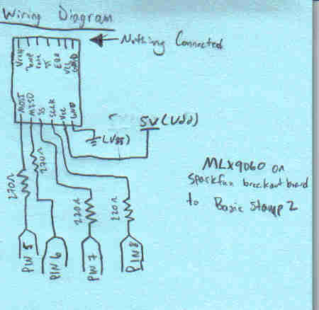
I have attached a wiring diagram and some links that I have already explored regarding this issue. Please ask if you need to know anything else!
Thanks for your help!
Links:
http://www.sparkfun.com/commerce/product_info.php?products_id=8372
http://webstore.mlxsemi.com/KnowledgeBase/MLX90609_basic_connections_978.aspx
http://www.melexis.com/Sensor_ICs_Inertia/Sensor_ICs_Inertia/Angular_Rate_Sensor_582.aspx
This is the code that I am currently using and does not work:
' {$STAMP BS2}
' {$PBASIC 2.5}
'this is a program designed to test the gyroscope and display its output
'---pin layout----
'pin 5 is orange is MOSI
'pin 6 is blue is MISO
'pin 7 is green is SS
'pin 8 is yellow is SCLK
'---Constants---
MOSI CON 5
MISO CON 6
SS CON 7
SCLK CON 8
'---Variables----
answer VAR Word
'----Program----
DO
HIGH SS
LOW SS
SHIFTOUT MOSI,SCLK,MSBFIRST,[noparse][[/noparse]%10010100\8] 'start ADC and set channel to 0 (GYRO CHANNEL)
HIGH SS
LOW SS
SHIFTOUT MOSI,SCLK,MSBFIRST,[noparse][[/noparse]%10000000\8] 'poll for reading
SHIFTIN MISO,SCLK,MSBPRE,[noparse][[/noparse]answer\16] 'save the answer in a variable
HIGH SS
answer=answer & %0000111111111110 'mask answer to extract data from ADC, we don't need the first 4 digits or the last onr (from left to right)
answer=answer >> 1 'shift the answer so that we dont display the LSB which is not part of the answer
DEBUG HOME,"Omega = ",DEC answer,11 'Display answer


Comments
▔▔▔▔▔▔▔▔▔▔▔▔▔▔▔▔▔▔▔▔▔▔▔▔
- Stephen