

Need help with a Uni Polar Motor
 blacksheep45
Posts: 41
blacksheep45
Posts: 41
Hello,
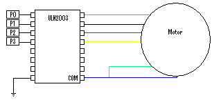
I am currently trying to connect a 48V unipolar motor to a BS2. I am using a ULN2003 darlington array driver chip. The wiring for the motor is as follows:
Phase 1 = Orange
Phase 2 = Black
Phase 3 = Red
Phase 4 = Yellow
The common wires are (Orange & White and Black & White) and (Red & White and Yellow & White)
I have connected the motor to the driver chip as can be seen in the attachment
The two common wires are blue and green because it was easier to do than having several different colours for the same wire.
The motor also has its own 48V, 5A·power·supply. The V+ of the supply is connected to the com pin of the driver chip and the V- is connected to ground.
When i try to run the program (the stepper motor program from the parallax website changed to use pins 0 - 3) both the driver chip and the basic stamp blow.
Can anyone help me with this?
Kind Regards
Shaun
Comments
I realize that the driver chip can only handle 500mA and my motor is trying to draw 4.5A per phase, but should this cause both the driver chip and the stamp to blow? as I was told by the motor manufacturer that if there was not enough current to be drawn the motor would simply not move.
Also I was wondering if anyone knew where I would be able to get a high current driver chip, preferably 5A or over.
Kind Regards
Shaun
▔▔▔▔▔▔▔▔▔▔▔▔▔▔▔▔▔▔▔▔▔▔▔▔
Tom Sisk
http://www.siskconsult.com
·
regards
Shaun
If you've got lots of uln2003's to get rid of, you should opto-isolate the stamp from the driver chip.
▔▔▔▔▔▔▔▔▔▔▔▔▔▔▔▔▔▔▔▔▔▔▔▔
Tom Sisk
http://www.siskconsult.com
·
Or would I be better off using another driver chip?
Cheers
Shaun
You can Google "high power stepper driver" to get some idea of what's involved.
▔▔▔▔▔▔▔▔▔▔▔▔▔▔▔▔▔▔▔▔▔▔▔▔
Tom Sisk
http://www.siskconsult.com
·