The Basic Stamp Tower
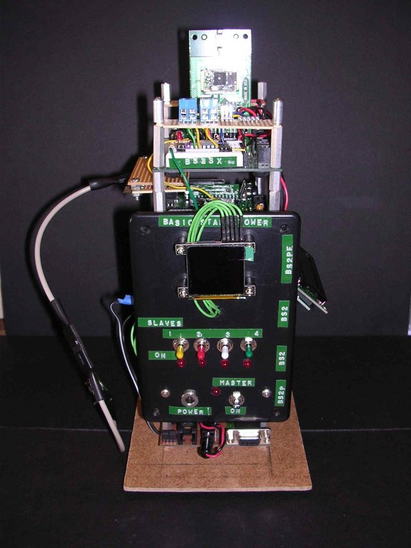
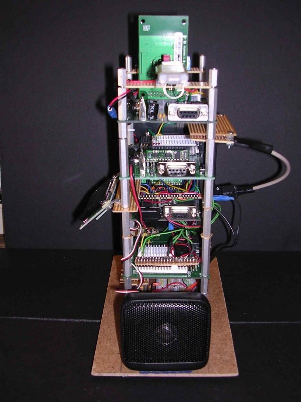
·· This project - The Basic Stamp Tower (BST) - is the direct result of humanoido's inspiration and imagination.· It can be viewed both as a contraction and expansion of his Basic Stamp "Supercomputer". A contraction, since there are only 5 processors as compared to 10+ in the BSSS. An expansion, in that it incorporates 4 different basic stamps, 2 math coprocessors, wireless capabilities, and multiple external storage options. My objective was to combine several different basic stamp development boards into a single unit, so that computing power could be distributed among multiple processors. The tower arrangement conceived by humanoido was ideal for this purpose. The BST consists of five stacked modules on a 5x8 inch base, communicating through a bidirectional single wire. As shown in the·attached photos (front & rear views), the front panel contains the power distribution switches and activity LEDs associated with each module as well as a uOLED. A rb500 bluetooth·accessory is inserted in the top module. The LCD is visible attached to the right side and an infrared temperature sensor is plugged into a port on the left side.· The rear view shows the placement of the speaker and the USB data logger attached to the top module.·A summary of the BST architecture follows.
·· Ground Floor - Module #1 - Master Computer
·BS2p 24/40 DEMO BOARD with added uM-FPU v2 (SPI mode) and 64K eeprom (I2C bus).· Ports are provided for debugging the FPU, extending the· BST net to other processors ·(e.g., Penguin),·connecting to additional I2C devices, and·accessing the LCD. Unlike the BSSC, the LCD is only controlled by the master. All unused pins are brought out to·self-powered ports to facilitate connecting to sensors and/r other acceseories. THis feature is common to all modules.
···2nd Floor - Module #2 - Slave #1
·BS2 HOMEWORK BOARD controlling a uOLED-128-GMD1 Display. Module #2 is dedicated to the uOLED color display. In addition to graphics and data display, it enables access to removable storage in the form of a micro SD card.
·· 3rd Floor - Module #3 - Slave #2
·BS2 populated CARRIER BOARD controlling an EMIC Speech Synthesis Board. Module #3 is dedicated to·interfacing with the EMIC and any processing involving sound generation. A connector on the carrier board facilitates attaching an external speaker.
·· 4th Floor - Module #4 - Slave #3
·BS2pe populated SUPER CARRIER BOARD dedicated to collecting data from sensors and other external devices. Ports are accessed through the application module connector.
·· 5th Floor - Module #5 - Optional
·BS2sx populated BOE BOARD with added uM-FPU v3, eb500 Bluetooth module, and Memory Stick Datalogger module.· Module #5 is dedicated to processing data which might be transferred from other modules. The eb500 provides wireless bidirectional communication with a PC through a terminal emulation program. The uFPU adds advanced floating point computation, in addition to temporary data storage in its embedded eeprom and two 12-bit ADC ports.· The USB datalogger adds additional removable storage in the form of a memory stick (currently, 1 GB).
··
·
··


Comments
··Attac hed find demo software in the form of 5 programs, one for each module, The demo is designed to exercise most of the hardware features of the BST, as well as demonstrate variations in communication between the modules. Please review the software for a more detailed description of module designs and the operational features of the software.
·· Future expansion will not be possible, due to height restrictions in our neighborhood. However, we were able to get permission to add a penthouse to the Basic Stamp Tower. Current plans are to add a SpinStamp populated basic stamp carrier board, dedicated to interfacing with 3.3 volt devices. We may also consider using the SpinStamp as the master computer.
I kind of have my own development tower going here also. Got some cutting boards and threaded rod.
▔▔▔▔▔▔▔▔▔▔▔▔▔▔▔▔▔▔▔▔▔▔▔▔
Mike2545
This message sent to you on 100% recycled electrons.
humanoido
please post your project in a new "Completed Projects" thread. I'm looking forward to learning more.
humanoido
I think you have inspired many people with your creation. You should be flattered. I simply posted my development platform to show support for this type of 'vertical tower electronics'. I don't think I will dedicate my unit for a collection of Stamps and sensors, instead I am using mine as an experimental platform. The space savings, wire management and close proximity in the tower makes sense as a multipurpose addition to my wireless breadboard. Parallax might consider putting something similar out, though it is easy enough to make yourself.
Thanks for the idea
▔▔▔▔▔▔▔▔▔▔▔▔▔▔▔▔▔▔▔▔▔▔▔▔
Mike2545
This message sent to you on 100% recycled electrons.
I have two ultra low cost versions of the "Tower framing," and will post more information at this thread.
http://forums.parallax.com/showthread.php?p=765140
humanoido
The cutting boards were purchased specifically for this project, I must say they machine very well.
▔▔▔▔▔▔▔▔▔▔▔▔▔▔▔▔▔▔▔▔▔▔▔▔
Mike2545
This message sent to you on 100% recycled electrons.
The Penthouse (Module #6) - SpinStamp populated BS2 Carrier Board
The attached photo (Penthouse) shows the top view of the carrier board. Three Digilent style ports (4 pins,grd,Vdd), two Parallax ports (1 pin, Vdd,grd), a power switch, a green power indicator led, and a red activity led have been added to the board. A Digilent PMOD-REG1 board is plugged into port 3, in order to provide an auxilary 3.3v power supply to power the ports (Vdd), while still allowing full access to the port.
The addition of a·SpinStamp module to the BST·allows potential access to 3.3v devices and enables basic stamps to utilize the video generation features of the propeller chip.· The attached·spin demo program demonstrates its use as a slave module.·Note that it was not possible to use a single wire bus, since the required 1K series resistor at the·propeller input pin·acted as a voltage divider with the·1K pull-down resistor on the BST bus, lowering the output signal to unacceptable values. Therefore, another pin on the SpinStamp was used as the input connection to the master (module #1).
The next step in the evolution of the BST project·will be to redesign the system so that the·SpinStamp will be the master.
Nick
humanoido
The attached figures, Scheme1 & Scheme2, show connection diagrams for the BST system with the Spin Stamp module programmed as a "slave and as the "master".· In the latter case, 2 wire communications are required for each BS2 module, all controlled by different cogs.· This design enables true parallel operation of the basic stamps.
I have selected JDCogSerial.spin as the serial object which is replicated in each of the 5 cogs assigned to the BS2 modules.· This serial object is compact and includes both receive and transmit buffers in cog memory.· The single wire communication bus is also retained, allowing intercommunication between BS2 modules if desired.· The receive lines associated with each cog have a dual function.· They serve as control lines signaling the master when a BS2 module has finished processing or has data ready for transmission to the master as well as a serial transmission line for data.· The attached demo programs (StampMaster.spin, Module1.bsp and Module4.bspe) show how this works. Assuming all programs have been loaded in their modules, the BS2 modules are first turned on and allowed to settle in their waiting state (the activity leds stop blinking) before the master is powered up.
The Spin Stamp functions to schedule and synchronize BS2 module operations, as well as manage data generated by these operations.· The BST may be programmed in many different configurations without changing connections, where the Spin Stamp or any BS2 module can function as slave, master, or neither.
This is an amazing upgrade to the BSTower and a job exceedingly
well done! Congratulations, and keep up these great additions.
I especially like the inventive concept of how the Spin Stamp can
can control each BS with a single Cog. I think these models with
multiple computers may have more autonomous self thinking
cores in the future. Already we see at least 3 muli-cored devices
with concepts of muli-function purposed for master-not master.
I like how you created two applications with two separate programs
to forge out differing creative concepts. My only request is a detailed
wiring schematic (in addition to the block diagram), so others can
reproduce your scientific results and create new versions of their own.
I look forward to seeing more of your fine work!
humanoido