Allegro's A6281 Driver and Brilldea's PolkaDOT product
 Timothy D. Swieter
Posts: 1,613
Brilldea has a new product coming out in a week or two (production has been ordered and we are waiting for delivery). The products name is PolkaDOT-51 and a PolkaDOT is an individually controllable pixel that can be daisy chained. The PolkaDOT-51 operates on 5 to 6V DC and requires four I/O lines for an SPI like interface. The PolkaDOT can accept 3 to 5V DC for the data input. The PolkaDOT-51 uses the Allegro MicroSystems A6281 which is a three channel, 10-bit per channel constant current LED controller. More information on the A6281 can be found here: www.allegromicro.com/en/Products/Part_Numbers/6281/index.asp One (of many) great features of this IC is that it is easy to daisy chain. Therefore the PolkaDOTs can be chained up to 250 units per chain.
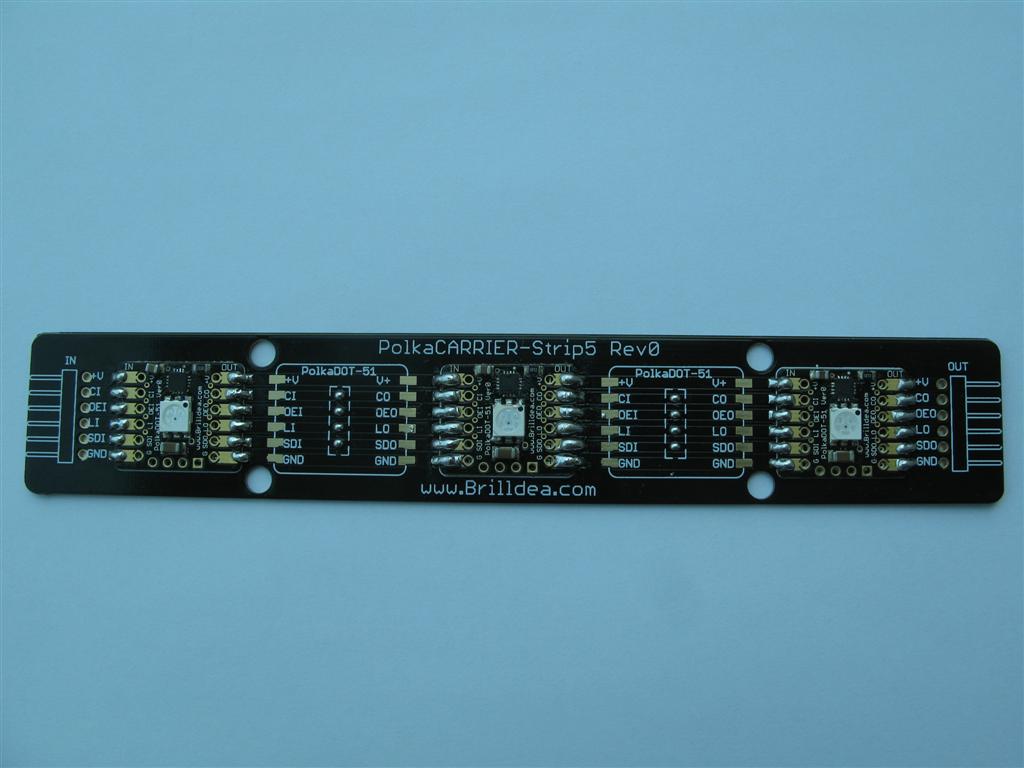
I attached pictures of the prototype units that I made. The soldering is OK and I had to do some touch up after the reflow oven, but they work. In addition to the PolkaDOT-51 I will be selling a PolkaCARRIER boards. One PolkaCARRIER is a strip which 5 PolkaDOTs can be soldered to and another is a block with an arrangement of 2x2. You could populate all spots on the PolkaCARRIER with a PolkaDOT, or you could use the solder jumpers as shown in the image. In time I will have a dedicated Propeller controller for the PolkaDOTs and I will also have a couple other PolkaDOT designs for 12V DC and over LED arrangements. The current PolkaDOT could have external LEDs connected via the four plated holes on the one edge - I plan to attach the RGB LED ribbon.
In order to control the PolkaDOTs I created a PASM driver. The driver is uploaded to the object exchange here: obex.parallax.com/objects/446/ The demo and driver code is well commented. I suspect that I will be updating the driver and demo code over the next week or so. If you have any feedback on what you see let me know so I can incorporate it. I imagine it should be easy to also control the PolkaDOT/A6281 from an SX or even a Basic Stamp.
Next on my to-do list is to setup a page on Brilldea's web site. Then create a data sheet followed by a couple videos showing off the product. I will keep this thread updated with the progress and availability. I anticipate the pricing of a PolkaDOT to be US$5.45 per unit or US$50.00 for 10 units and maybe another discount at 100+ units. I have several projects in mind for using the PolkaDOT of which one will be remaking my Living Room LED system.
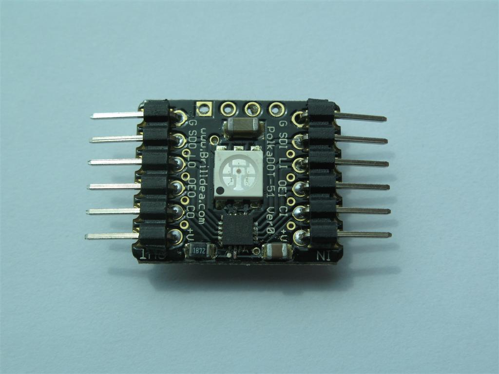
img_0249: A PolkaDOT-51 with right angle headers added.
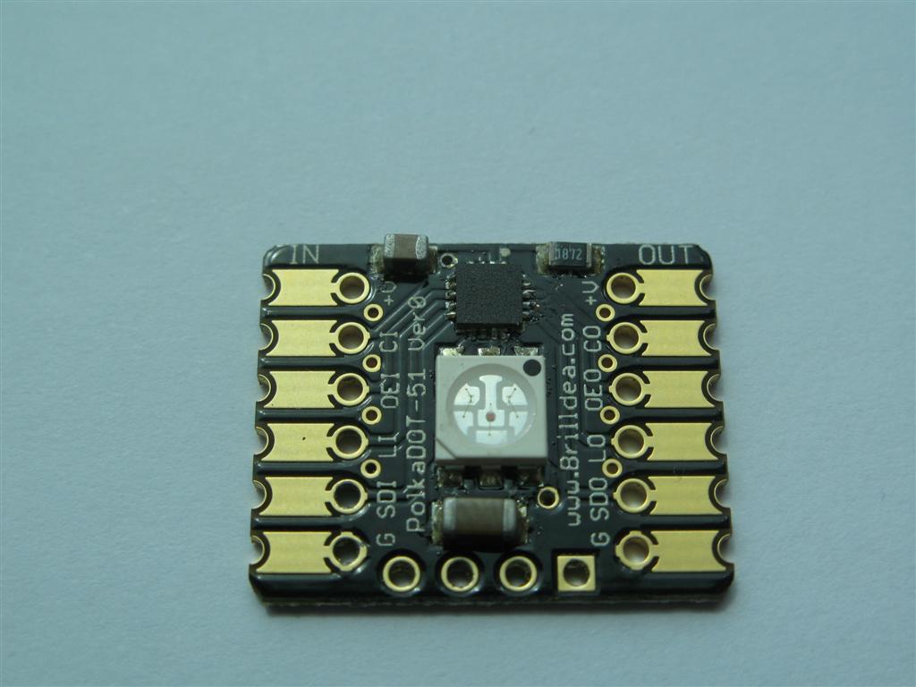
img_0252: A PokaDOT-51 with headers. There are solder pads on the top and bottom as well as a plated edges in the cup area.
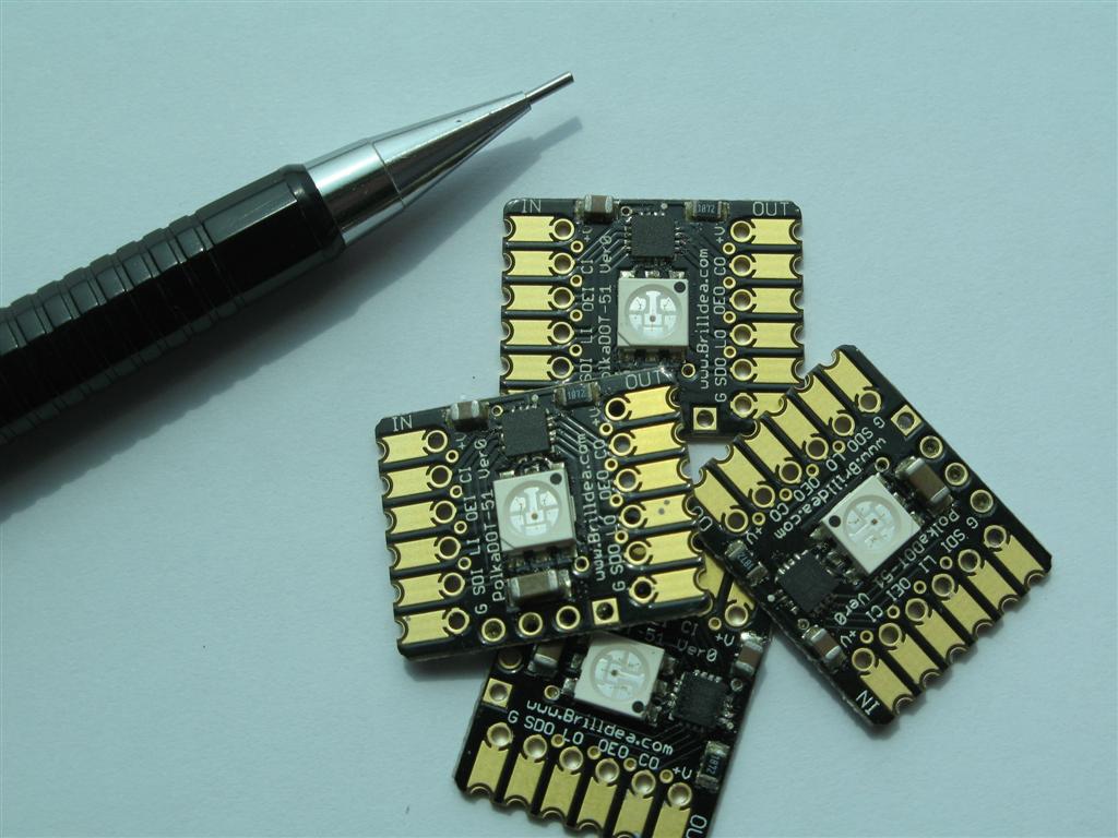
img_0267: You can get an idea with size here, they are about the size of a USA Quarter coin.
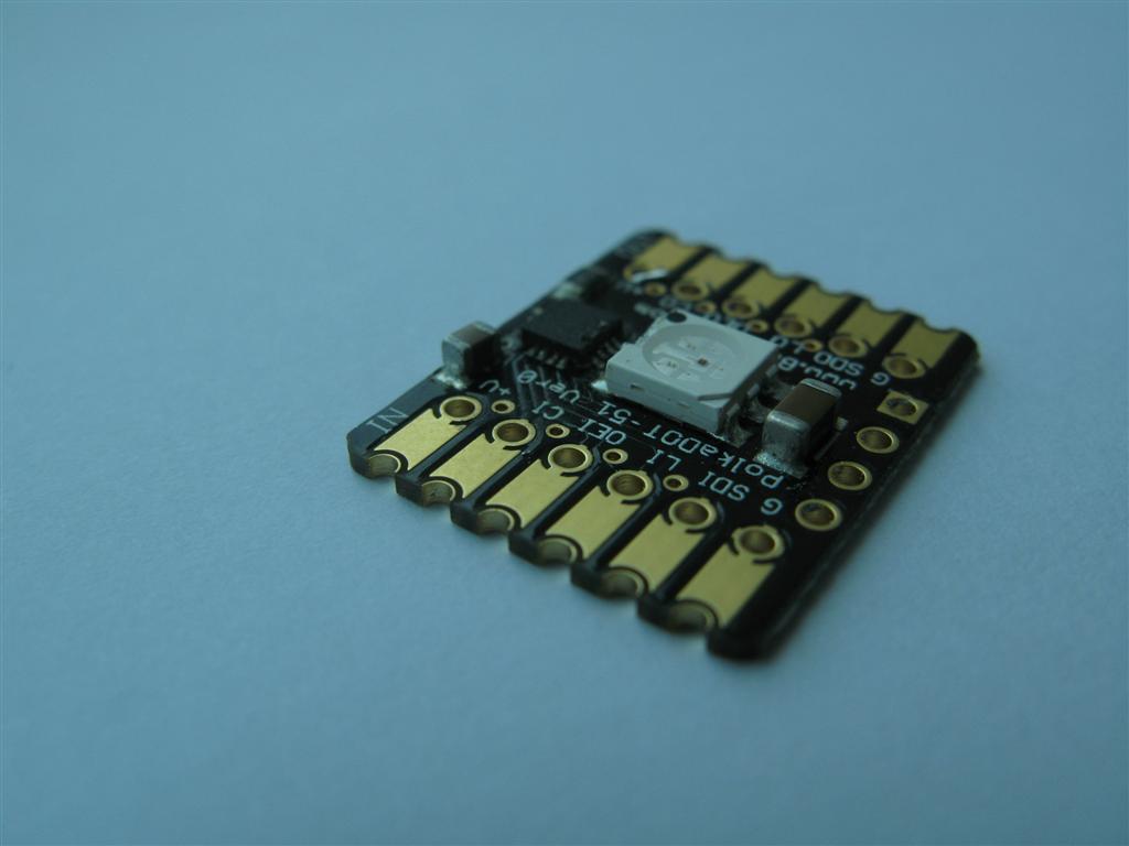
img_0494: Here you can see the plated edges. Unfortunately there was a design flaw so the plated edge doesn't connect with the plated finger. This will be fixed in the next revision. In the mean time a simple solder bridge works. See pictures below.
img_0487: Three PolkaDOT-51s soldered to a PolkaCARRIER. The carrier could take five, but I wanted to space them out here so for the unused portions there is a place to solder bridge to pass the connections through. Notice how the solder is bridged from the edge up onto the fingers.
▔▔▔▔▔▔▔▔▔▔▔▔▔▔▔▔▔▔▔▔▔▔▔▔
Timothy D. Swieter, E.I.
www.brilldea.com - Prop Blade, LED Painter, RGB LEDs, 3.0" LCD Composite video display, eProto for SunSPOT
www.tdswieter.com


Comments
img_0301: A test jig I built using the Propeller Protoboard. The PolkaDOT to be tested is placed on the pogo pins. Then it is pressed down. The test starts when that one pin that is below all the others makes contact with the device under test.
img_0310: Testing a PolkaCARRIER.
img_0257: The PolkaCARRIER-Block4 - a 2x2 arrangement.
img_0237: The first round of code testing and writing was using the Propeller Demo board. Here I stuck a PolkaDOT in the I/O pins on the left and wired the 5V DC over (the blue wire).
img_0304: Another shot of testing on the test jig.
I got a video montage uploaded to YouTube. When it is done processing it will be available here: www.youtube.com/watch?v=LPxTfiJkolQ
To Do in the core driver:
-implement the ci to li delay for a pixel chain per what the data sheet says - the driver is calculating the delay (needs to be verified) but it isn't implementing it yet.
▔▔▔▔▔▔▔▔▔▔▔▔▔▔▔▔▔▔▔▔▔▔▔▔
Timothy D. Swieter, E.I.
www.brilldea.com - Prop Blade, LED Painter, RGB LEDs, 3.0" LCD Composite video display, eProto for SunSPOT
www.tdswieter.com
Post Edited (Timothy D. Swieter) : 4/11/2009 11:30:59 PM GMT
▔▔▔▔▔▔▔▔▔▔▔▔▔▔▔▔▔▔▔▔▔▔▔▔
Timothy D. Swieter, E.I.
www.brilldea.com - Prop Blade, LED Painter, RGB LEDs, 3.0" LCD Composite video display, eProto for SunSPOT
www.tdswieter.com
▔▔▔▔▔▔▔▔▔▔▔▔▔▔▔▔▔▔▔▔▔▔▔▔
JMH
▔▔▔▔▔▔▔▔▔▔▔▔▔▔▔▔▔▔▔▔▔▔▔▔
Timothy D. Swieter, E.I.
www.brilldea.com - Prop Blade, LED Painter, RGB LEDs, 3.0" LCD Composite video display, eProto for SunSPOT
www.tdswieter.com
I also have a couple improvements to make to the driver. The one in the object exchange is good, but there are more details to add to it so I hope to do that by the end of the weekend.
▔▔▔▔▔▔▔▔▔▔▔▔▔▔▔▔▔▔▔▔▔▔▔▔
Timothy D. Swieter, E.I.
www.brilldea.com - Prop Blade, LED Painter, RGB LEDs, 3.0" LCD Composite video display, eProto for SunSPOT
www.tdswieter.com
▔▔▔▔▔▔▔▔▔▔▔▔▔▔▔▔▔▔▔▔▔▔▔▔
Timothy D. Swieter, E.I.
www.brilldea.com - Prop Blade, LED Painter, RGB LEDs, 3.0" LCD Composite video display, eProto for SunSPOT
www.tdswieter.com
Next up, more changes for the Propeller driver, plus a project that will use a Propeller as the heart of the system. I am thinking I may have to make a new driver where multiple chains are controled using the same clock, output enable and latch lines (a unique data line per chain).
▔▔▔▔▔▔▔▔▔▔▔▔▔▔▔▔▔▔▔▔▔▔▔▔
Timothy D. Swieter, E.I.
www.brilldea.com - Prop Blade, LED Painter, RGB LEDs, 3.0" LCD Composite video display, eProto for SunSPOT
www.tdswieter.com
I don't know how you are "snapping" apart your boards. But at my work we used to do it by hand and we started having problem with cracked componets. So we got a "Maestro 3" by CAB technologies. http://www.olamefusa.com/e_maestro3e.htm
It was expensive (a couple grand new), but it is very slick. You can seperate 10 panels in a matter of seconds, and it doesn't stress the componets. If you are able to get one "on the cheap" it is worth having.
P.S. for the pictures with header pins, you should put female headers on the output side, then you can just connect as many as you want together.
Bean.
▔▔▔▔▔▔▔▔▔▔▔▔▔▔▔▔▔▔▔▔▔▔▔▔
- - - - - - - - - - - - - - - - - - - - - - - - - - - - - - -
There is a fine line between arrogance and confidence. Make sure you don't cross it...
·
You are right about the headers too. The part comes without any headers so the client can add which ever type they want or none at all and surface mount it. The one in the picture has both male headers because I am sourcing some cables that have female on both ends. I could cook up an experiment with the male/female and take some pictures to inspire others.
▔▔▔▔▔▔▔▔▔▔▔▔▔▔▔▔▔▔▔▔▔▔▔▔
Timothy D. Swieter, E.I.
www.brilldea.com - Prop Blade, LED Painter, RGB LEDs, 3.0" LCD Composite video display, eProto for SunSPOT
www.tdswieter.com
http://www.harborfreight.com/cpi/ctaf/Displayitem.taf?itemnumber=90757
Some have gotten comparable shears by way of Ebay for about $50.
▔▔▔▔▔▔▔▔▔▔▔▔▔▔▔▔▔▔▔▔▔▔▔▔
Timothy D. Swieter, E.I.
www.brilldea.com - Prop Blade, LED Painter, RGB LEDs, 3.0" LCD Composite video display, eProto for SunSPOT
www.tdswieter.com
▔▔▔▔▔▔▔▔▔▔▔▔▔▔▔▔▔▔▔▔▔▔▔▔
Timothy D. Swieter, E.I.
www.brilldea.com - Prop Blade, LED Painter, RGB LEDs, 3.0" LCD Composite video display, eProto for SunSPOT
www.tdswieter.com
Now, just for clarification, the PolkaDOT-51 does come with the RGB LED installed, but the PolkaCARRIER-Strip5 and PolkaCARRIER-Block4 are PCB only (i.e., no RGB LED installed), correct? If so, will you be selling the RGB LEDs individually for installation on the PolkaCARRIER-Strip5 and PolkaCARRIER-Block4?
The PolkaDOT-51 is a complete module with all SMT components including the IC, resistor, capacitors and the RGB LED. Buy the module, hook it up, download the code and you are good to go.
The PolkaCARRIERs are bare PCBs in which the entire PolkaDOT assembly is attached to the PCB. The PolkaCARRIERs are in place of running wires in between each module. The PCBs are bare - no components and it is designed to have the PolkaDOT-51 assembly soldered straight to the carrier. I am also working on sourcing cables of various sizes, but for now you will have to supply your own cables/wires or use a PolkaCARRIER.
▔▔▔▔▔▔▔▔▔▔▔▔▔▔▔▔▔▔▔▔▔▔▔▔
Timothy D. Swieter, E.I.
www.brilldea.com - Prop Blade, LED Painter, RGB LEDs, 3.0" LCD Composite video display, eProto for SunSPOT
www.tdswieter.com
Sort of off-topic but they could have used Tim's stuff...
Right, you could use the PolkaDOT and then you could change the LED colors on each sheep - a rainbow brite sheep! Next step is to add a 900MHz radio from Parallax and then you can remote command the colors on each sheep. The next step after that would be to add the GPS receiver and some file reading capability, then it wouldn't matter which sheep is where and you could still then "paint" on them based on location or just a canvas tied to a computer paint program or similar. Similarly you could have the sheep change color based on where it was standing.
I haven't seen any sheep here in Hong Kong or else I may be tempted to try this. I will keep my eyes open for any sheep while I travel to Shanghai and to the USA!
▔▔▔▔▔▔▔▔▔▔▔▔▔▔▔▔▔▔▔▔▔▔▔▔
Timothy D. Swieter, E.I.
www.brilldea.com - Prop Blade, LED Painter, RGB LEDs, 3.0" LCD Composite video display, eProto for SunSPOT
www.tdswieter.com
Thanks for the clarification on the PolkaCarriers. In some of the photos it was hard to tell that there is a PolkaDOT was mounted on the carrier board because the profile is so small, but now that you pointed it out it's obvious. I'm looking forward getting a few PolkaDOTs for testing.
I have noticed that they are sensitive to EMI; last year at Maker Faire, there was a Tesla coil across the room which interfered a lot, and I only had 2 inch cables. The A6281 also has a flaw that I've brought up with Allegro and haven't gotten any response yet. There are two bits in the control word which are labeled "ATB" and the datasheet simply says they are used during testing, and not to use them. If a spurious pulse somehow gets onto the data lines, one of these bits might be activated. This makes some weird colors and flashing appear, and it also kills the outbound buffers. You have to clear the ATBs in a ShiftBrite/PolkaDOT before you can clear the ATBs in the next device. If you have 50 devices in a row, that means you have to shift out to the whole string 50 times before you've recovered from interference. It's advisable to always write the control registers alternately with the PWM registers. If you're updating at 100 Hz then a string of 50 will recover in half a second, though you'll still see a wipe effect as the ATBs cascade.
The ideal application for these devices are more than three pixels and less than 50 pixels, or when the pixels need to be spread out but still can be wired together. It doesn't make much sense to have only one ShiftBrite or PolkaDOT, you need a microcontroller anyway and you could just hang a single RGB LED from microcontroller PWM and save an I/O line.
Tesla Coils are interference monsters!!! I was creating the hardware and software for a major Hollywood theme park that used a massive tesla coil in the show. A lot of extra care had to be done to be sure that things were properly grounded and handled, especially with pyro mounted nearby!! We certainly didn't want any funny business going on.
One could possible used twisted lines to help with some of the noise or even shielded lines if it was a big problem.
I was going to experiment with the Allegro Test Bits when I had a moment just because I am curious what it does. It looks like you might have saved the time for me to do it.
▔▔▔▔▔▔▔▔▔▔▔▔▔▔▔▔▔▔▔▔▔▔▔▔
Timothy D. Swieter, E.I.
www.brilldea.com - Prop Blade, LED Painter, RGB LEDs, 3.0" LCD Composite video display, eProto for SunSPOT
www.tdswieter.com