APPLICATION DEMO: Calibrating the HM55B Compass using code from the OBEX
 Beau Schwabe
Posts: 6,576
Here is a brief explanation on what to do and how to calibrate the HM55B Compass module.
·
1)·Get the latest program from the OBEX located here... http://obex.parallax.com/objects/48/
·
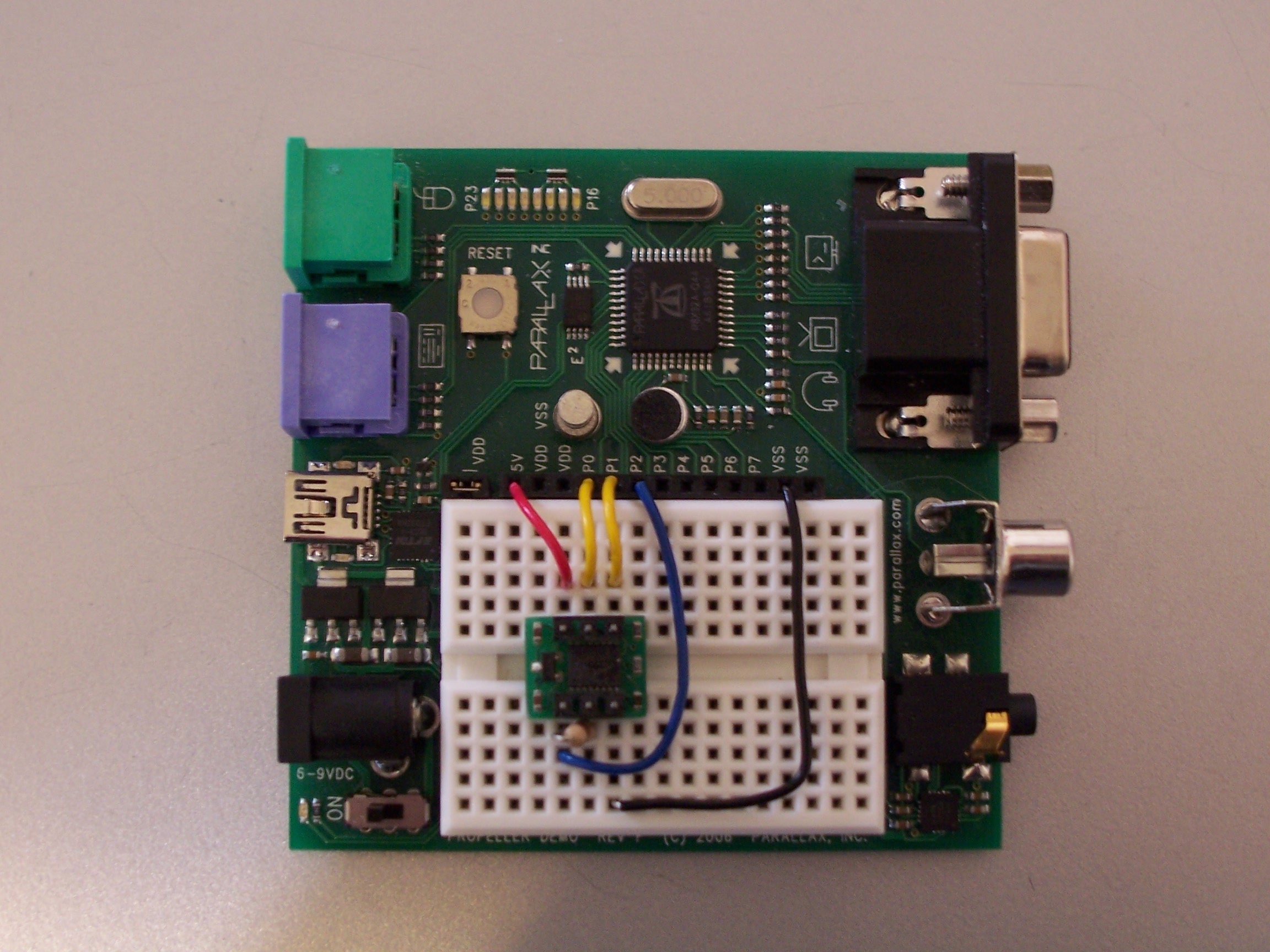
2) Build the Circuit for the Propeller to communicate with the Compass. (schematic details can be found within the Serial or TV SPIN files from the OBEX)

·
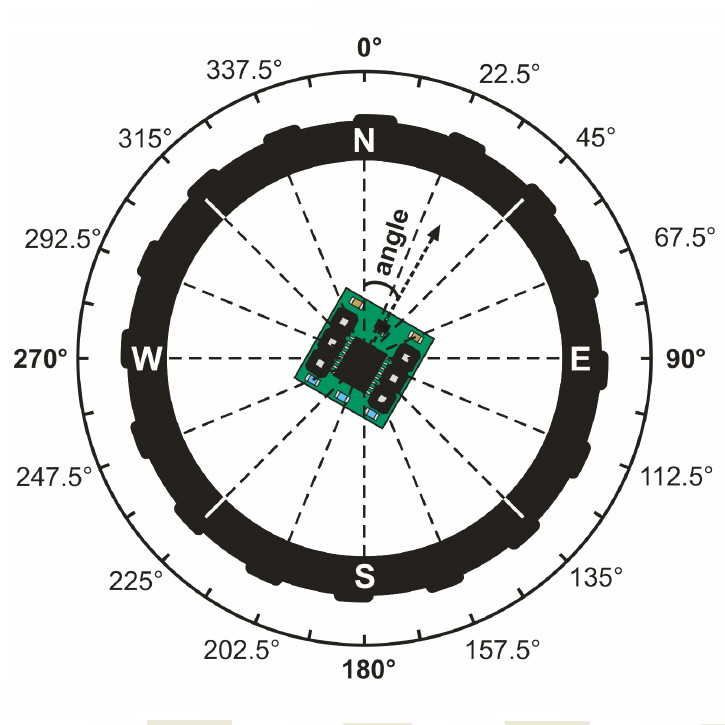
3)·Print·the compass image attached to this post, or download the HM55B documentation from the product page located here... http://www.parallax.com/Portals/0/Downloads/docs/prod/compshop/HM55BModDocs.pdf
·· ... and print page 3 from the PDF.

·
4) Do you know where North is?· I guess that's sort of the point here using a compass isn't it?· Ok, to avoid the Chicken and the Egg scenario, you'll need to determine North either by way of a store bought compass, or lodestone suspended by a string.
·
5) Once you are sure·which direction·North is, orient and secure the print-out from step #3 ... I taped mine to a cardboard box away from any metallic objects or my computer.
·
6) Double check all of your wiring and run the Spin program called·... 'HM55B Compass Module Serial DEMO· V1.1'· ... by pressing F10
·
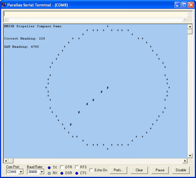
7) Start the Parallax serial terminal (PST.exe), you should see a screen similar to this one...

·
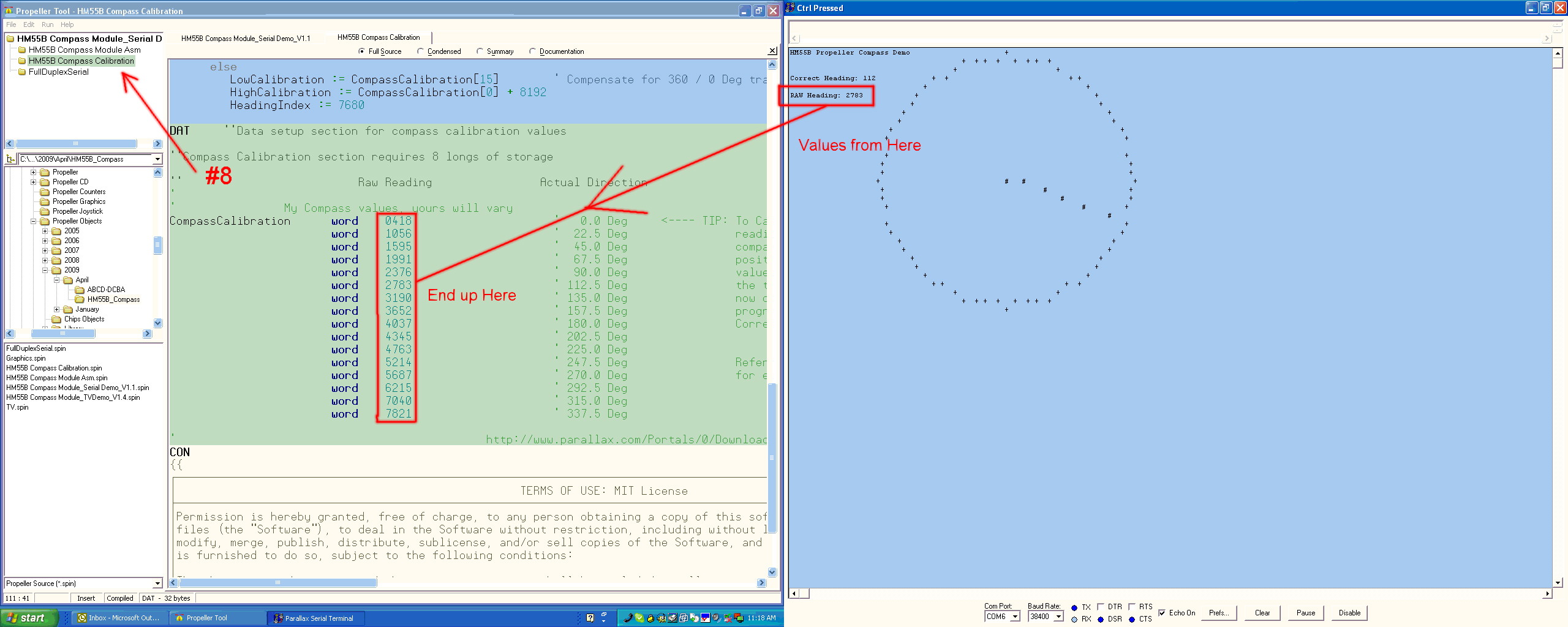
8) Open the program TAB 'HM55B Compass Calibration' by clicking on the program tree located on the left hand side of the Propeller IDE.
·
9) Scroll down to the very bottom of the 'HM55B Compass Calibration'
·
If you have made it this far, the hard part is over
·
10) Point the Demo Board (with compass) in each direction indicated on the print-out.· (There are a total of 16 positions)· For each position make note of the RAW value displayed from the PST and enter·the value into the corresponding "word" position in the 'HM55B Compass Calibration' program.
·
11)· After you have entered in all 16 positions, that's it, you’re done; the 'HM55B Compass Calibration' program is now calibrated to your compass module.

·
Note: from step #10 , it might be easier to write down all of the RAW values first, and then enter them into 'HM55B Compass Calibration' at a later time.
·
·
Running the Program without the DEMO program:
·
·
Setup Block:
Initialization·Block
Main Program Block
·
Basically after setup and initialization, you read the RAW heading directly from the Compass module, and then pass it through the Calibration program which in turn provides an output of the correct heading.
Going Further ...·The·DEMO program with TV output provides a different feel than the serial ASCII version.
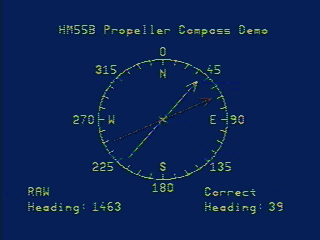
This object is also included with the OBEX download.· Simply run the 'HM55B Compass Module_TVDemo_V1.4.spin'·and connect a TV to the video output on the Propeller Demo board instead.· The TV output shows two Compass Arrows indicating the RAW·direction before calibration in "RED" and at the same time it shows the corrected heading after calibration in 'YELLOW'.

·
·
··
▔▔▔▔▔▔▔▔▔▔▔▔▔▔▔▔▔▔▔▔▔▔▔▔
Beau Schwabe
IC Layout Engineer
Parallax, Inc.
Post Edited (Beau Schwabe (Parallax)) : 4/8/2009 10:13:38 PM GMT
·
1)·Get the latest program from the OBEX located here... http://obex.parallax.com/objects/48/
·
2) Build the Circuit for the Propeller to communicate with the Compass. (schematic details can be found within the Serial or TV SPIN files from the OBEX)
·
3)·Print·the compass image attached to this post, or download the HM55B documentation from the product page located here... http://www.parallax.com/Portals/0/Downloads/docs/prod/compshop/HM55BModDocs.pdf
·· ... and print page 3 from the PDF.
·
4) Do you know where North is?· I guess that's sort of the point here using a compass isn't it?· Ok, to avoid the Chicken and the Egg scenario, you'll need to determine North either by way of a store bought compass, or lodestone suspended by a string.

·
5) Once you are sure·which direction·North is, orient and secure the print-out from step #3 ... I taped mine to a cardboard box away from any metallic objects or my computer.
·
6) Double check all of your wiring and run the Spin program called·... 'HM55B Compass Module Serial DEMO· V1.1'· ... by pressing F10
·
7) Start the Parallax serial terminal (PST.exe), you should see a screen similar to this one...
·
8) Open the program TAB 'HM55B Compass Calibration' by clicking on the program tree located on the left hand side of the Propeller IDE.
·
9) Scroll down to the very bottom of the 'HM55B Compass Calibration'
·
If you have made it this far, the hard part is over
·
10) Point the Demo Board (with compass) in each direction indicated on the print-out.· (There are a total of 16 positions)· For each position make note of the RAW value displayed from the PST and enter·the value into the corresponding "word" position in the 'HM55B Compass Calibration' program.
·
11)· After you have entered in all 16 positions, that's it, you’re done; the 'HM55B Compass Calibration' program is now calibrated to your compass module.
·
Note: from step #10 , it might be easier to write down all of the RAW values first, and then enter them into 'HM55B Compass Calibration' at a later time.
·
·
Running the Program without the DEMO program:
·
·
Setup Block:
CON ''General Constants for Propeller Setup
    _CLKMODE = XTAL1 + PLL16X
    _XINFREQ = 5_000_000

CON ''Setup Constants for the Compass
    Enable = 0
    Clock = 1
    Data = 2

{{
            ┌────┬┬────┐
      ┌────│1  6│── +5V       P0 = Enable
      │ 1K  │  ├┴──┴┤  │               P1 = Clock
  P2 ┻──│2 │ /\ │ 5│── P0        P2 = Data
            │  │/  \│  │
    VSS ──│3 └────┘ 4│── P1
            └──────────┘
}}

VAR ''Setup variables related to the compass
    long RawHeading, CorrectHeading

OBJ ''Setup Object references that make this demo work
    HM55B : "HM55B Compass Module Asm"
    Calibrate : "HM55B Compass Calibration"
Initialization·Block
HM55B.start(Enable,Clock,Data) '' Initialize Compass Object
Main Program Block
RawHeading := HM55B.Theta ' Read RAW 13-bit Angle
CorrectHeading := Calibrate.Correct(RawHeading) ' Calibrate Correct Heading
·
Basically after setup and initialization, you read the RAW heading directly from the Compass module, and then pass it through the Calibration program which in turn provides an output of the correct heading.
Going Further ...·The·DEMO program with TV output provides a different feel than the serial ASCII version.
This object is also included with the OBEX download.· Simply run the 'HM55B Compass Module_TVDemo_V1.4.spin'·and connect a TV to the video output on the Propeller Demo board instead.· The TV output shows two Compass Arrows indicating the RAW·direction before calibration in "RED" and at the same time it shows the corrected heading after calibration in 'YELLOW'.
·
·
··
▔▔▔▔▔▔▔▔▔▔▔▔▔▔▔▔▔▔▔▔▔▔▔▔
Beau Schwabe
IC Layout Engineer
Parallax, Inc.
Post Edited (Beau Schwabe (Parallax)) : 4/8/2009 10:13:38 PM GMT


Comments
▔▔▔▔▔▔▔▔▔▔▔▔▔▔▔▔▔▔▔▔▔▔▔▔
Toys are microcontroled.
Robots are microcontroled.
I am microcontrolled.
The Parallax Serial terminal is designed to work with the Propeller in a similar way that the DEBUG terminal works with the Basic StampII.
I have updated the link in my post (thank you I menat to do that anyway), but you can find the PST.exe program here ... http://www.parallax.com/tabid/442/Default.aspx
▔▔▔▔▔▔▔▔▔▔▔▔▔▔▔▔▔▔▔▔▔▔▔▔
Beau Schwabe
IC Layout Engineer
Parallax, Inc.
I've attached a zip file that includes a new version 1.1 of the compass calibration object in which I've completely rewritten the DetectRange subroutine so that it doesn't have this problem. The new code is actually simpler (more comments but fewer 'if' statements) and hopefully more reliable.
(I had to take the spaces out of the file name because it crashed the attachment manager when there were spaces in the file name.)
Edit: Don't use the one that was attached here; it has a different bug. Use the new one from my post two posts down from here. Thanks.
Post Edited (Dennis Ferron) : 4/11/2009 7:31:31 PM GMT
Thanks, I'll take a look at it and update the OBEX
▔▔▔▔▔▔▔▔▔▔▔▔▔▔▔▔▔▔▔▔▔▔▔▔
Beau Schwabe
IC Layout Engineer
Parallax, Inc.
Attached is the final, fully corrected version. You can run through the entire 360 degrees without any "unexpected jumps";
Dennis is correct about·residual magnetism in the device, but much of it depends on the environment and the geographical location.· The natural occurring Earth magnetism·itself is not perfectly balanced and can skew the readings.· Geographic’s makes a difference also... If you were to map out the apparent magnetic strength similar to that of a Smith chart, you'd see·the pattern shift depending on where you were geographically.
·
The Calibration is to help counter some of these anomalies and to gain a certain degree of precision.· The default values directly from the compass are fine for a general heading, but if you want increased resolution, each unit must be calibrated.
·
·
▔▔▔▔▔▔▔▔▔▔▔▔▔▔▔▔▔▔▔▔▔▔▔▔
Beau Schwabe
IC Layout Engineer
Parallax, Inc.
Even after calibration I can't get a fixed value. What could be the problem?
Thank you.
How is your sensor positioned, is it horizontal to the ground?... are there any devices that would cause any interference? i.e. motors, relay's, etc...
It is normal for the readings to fluctuate some, can you describe in more detail what you are observing?
▔▔▔▔▔▔▔▔▔▔▔▔▔▔▔▔▔▔▔▔▔▔▔▔
Beau Schwabe
IC Layout Engineer
Parallax, Inc.
Sorry for my english.
I hope you can help me.
The HM55B is only accurate to 6-bit (64-direction) resolution after calibration anyway... this equates to 5.625 Deg
The capacitor helps to stabilize the power to the HM55B by filtering out any power noise.
I worked this out once:
Even though you read in the data at 11 bits, the HM55B has a magnetic field range of +/-180 uT with a MAXimum 1.6 LSB/ uT
So that's only 8 bits right there (360/ 1.6) minus 1 bit of error for the LSB due to nyquist and you only have 7 bits per channel.
When you combine the two channels to produce a heading, you compound the amount of error into 2 bits of error and end up with 6 bits
of accuracy.
Reference:
http://www.parallax.com/StoreSearchResults/tabid/768/txtSearch/Compass/List/0/SortField/4/ProductID/98/Default.aspx
http://www.parallax.com/Portals/0/Downloads/docs/prod/compshop/HM55BDatasheet.pdf
▔▔▔▔▔▔▔▔▔▔▔▔▔▔▔▔▔▔▔▔▔▔▔▔
Beau Schwabe
IC Layout Engineer
Parallax, Inc.