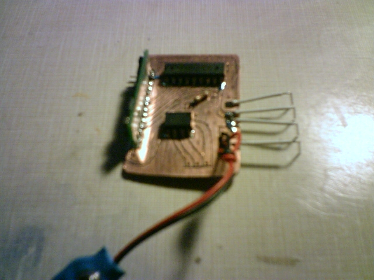
Need help with a charger(Closed)
Hi Guys,
First time every using the BS1. So before I declare it fried I thought I would let someone else give it look!
Input voltage is 9 to 10 volts with no Battery to load it down. Have not gotten far enough to tell what it will be under a load (Probably 8 to 9.5)
Anyway the idea was to use the darlington array to power the ds1620 and control current to the battery!
Problem one: the attached test routine debugs as expected, however the pin voltage stays near 0 volts. The ground pin on the temp sensor stays around 2.4 volts so I assume with a difference off 2.5 volts it is considered to be off below 2.7 volts.
The really weird problem is Pins 0 to 2. If I change the pin being switched in the routine to one of these: When high the debug terminal fails and will only work when the pins are returned low.
And same as the Pwr pin, the voltage doesn't change.
PS. Not shown on the schematic is a .1uF cap under the ds1620.
Post Edited (bambino) : 3/31/2009 2:13:49 AM GMT


Comments