

LED issues
 raejj
Posts: 14
raejj
Posts: 14
Hi all,
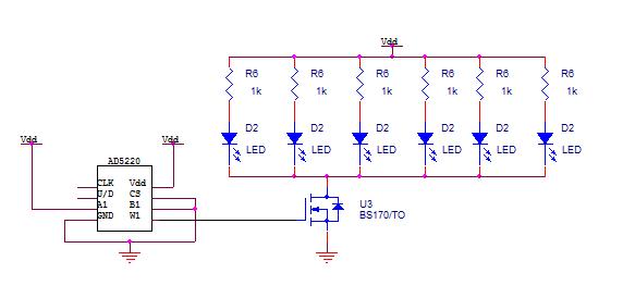
I'm having difficulty getting any response from my led circuit. I have a green led in series with a 120 ohm resistor. This is in parallel with five other led-resistor combinations. This is driven by a 2n2222a transistor. The base of the transistor is connected to the digital pot ad5220. Here is the schematic below. Does anyone have any suggestions as to why it doesn't work? I would greatly appreciate any input.
Thanks in advance.
572 x 274 - 17K
Comments
if I am reading the schematic corectly all the LEDS are on or off at the same time you are using the pot to regulate intensity?
·
-Phil
I apologize for the schematic. I was really in a rush and forgot to update it. Anyways, I checked the LED direction and they are all correct. Even if you cut them, there is a flat edge on the capsule indicating that side is the cathode. To answer your questions, I am using the Basic Stamp 2 to control the pot. And yes, I have all the LEDs on and off at the same time. Thanks for the suggestions on debugging. I'll have to try it.
Mike, the digital pot is 10k. I changed the resistance to 120 ohms and from the calculations, I got a current of 18.333mA flowing through the LED. Using KCL, the current through the collector is roughly 110 mA. With a beta of 100 (worst case), the base current would be 1.1 mA. Is this current too large with the resistor at the base being 50k?
Phil, you are so right. I connected a 50k resistor to the transistor 2N2222a. Do you know it could work with a mosfet BS170? That was my original plan but I realized there would be no voltage divider across the base of the mosfet.
The 2N2222A will not saturate with a 50K base resistor and your LED's will stay dim at best. You can calculate the base current required· to saturate the transistor using the Stamp specification for·VOH· and the 2N2222A specifications for hfe and VCEsat·.
▔▔▔▔▔▔▔▔▔▔▔▔▔▔▔▔▔▔▔▔▔▔▔▔
························ Craig Eid
··········· Triad Research and Development
Electical Engineering Design and Consulting Services
··················· www.TriadRD.com