

Buzzer 555 Timer Circuit from SX
 Chicago Mike
Posts: 88
Chicago Mike
Posts: 88
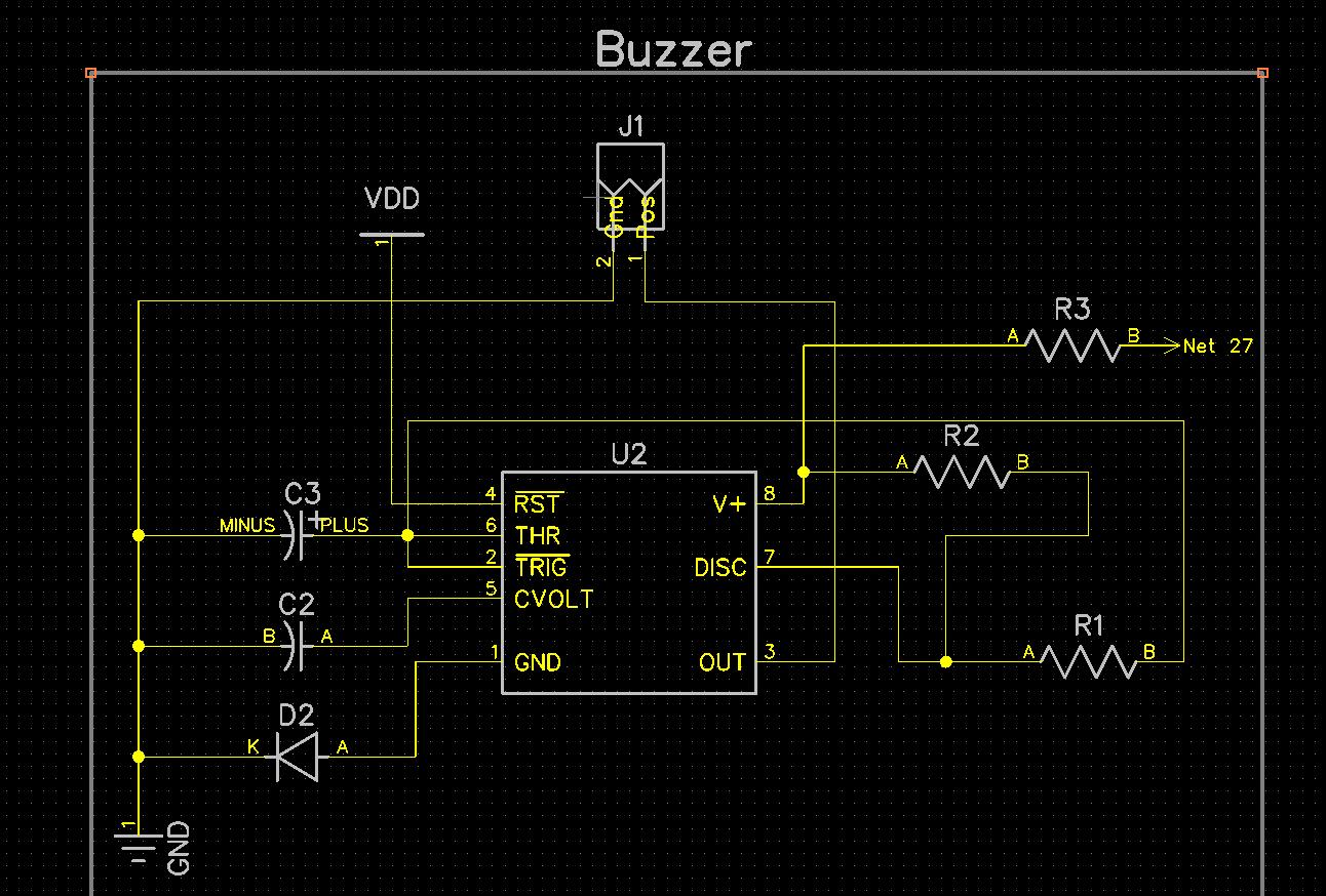
So attached you'll see a schematic to trigger a 5V Buzzer via a 555 timer circuit from an SX pin. (Thats what Net27 is).
This seems to work on a breadboard. The reason I'm using the timer is I want to make the buzzer alternate on and off. which I can change R1 and R2 to change the alternation timing. My question is, the datasheet for the 555 seems to lead me to believe I do not need to drive the 555 from a transisitor amplifer to do what i'm doing. Basicly, I'm driving it from the SX. Does this seem right? My buzzer is well under 10ma draw? Does this schematic look right to do this?
R3=10K
Incidently, I had to add D2 as it seemed that when I triggered this circuit without it, it would short the rail supply and reboot the SX? NOt quite sure why but this diode (1N4001) solved it. I'd be curious if anyone has some insight into what was going on here to require this?
Thanks again! Gotta love the SX and parallax!
Post Edited (Chicago Mike) : 3/19/2009 2:25:32 AM GMT
1292 x 874 - 189K
Comments
Have you considered using interrupts on the SX to control your buzzer?
What you're looking for is a gated oscillator, to enable/disable the 555's output.· This can be done by adding a MOSFET to the standard astable circuit (see attached.)