

Moving 1-wire device to parastic power
 patches
Posts: 15
patches
Posts: 15
Forgive the newbie question, I've searched quite a bit but haven't found the info I'm looking for. I think I'm dealing with a project that is a little too complicated for my experience level, which is fun, but frustrating. Most people using 1-wire chips seem to know their way around electrical circuits better than I do.
Anyway, I'm using multiple DS18S20 chips for a home control application (moving heat around to try to see how much I can reduce my energy use)
I have successfully figured out how to address multiple DS18S20 devices on the same pin and pull the temperature data out of them - at this point the project is entirely usable. But I'd like to use the parasitic power feature of the DS18S20 if I could - seems like a waste to run a couple hundred feet of 3-conductor wire around the house when 2-conductor would do.
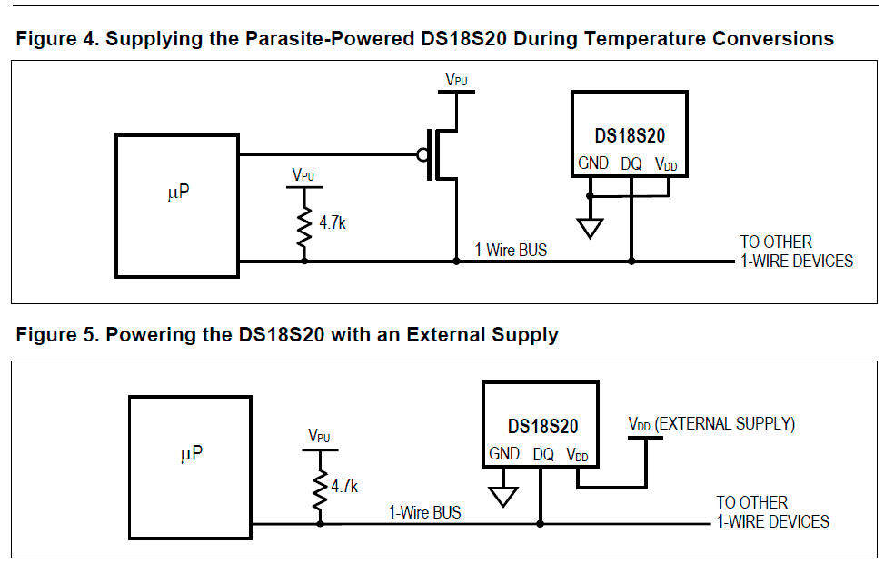
I have two questions- how do I change the physical connections, and how do I change the software. I know thats pretty all-encompassing, sorry. Attached is the datasheet hookup diagram.
My first problem is I can't make sense of figure 5, even though I've got thing working just fine. My current connection:
Vdd pin on the DS18S20 is connected to Vdd
GND pin on the DS18S20 is connected to Vss
DQ pin on the DS18S20 is connected to Pin15 (OWpin)
In addition, The Vdd pin is connected to the DQ pin via a 4.7K resistor
Assuming that is correct, and I just can't figure out how to read the schematic, I think the only physical change I have to make to run off parasitic power is to connect the Vdd pin to GND/Vss instead of conencting it to Vdd. The rest of the modifications would be software. Is this correct?
I'm pretty sure the only changes that need to be made to the code are using the HIGH and LOW commands, and some timing changes, but I can't figure out how to do it. The relevant part of my code is:
Anyway, I'm using multiple DS18S20 chips for a home control application (moving heat around to try to see how much I can reduce my energy use)
I have successfully figured out how to address multiple DS18S20 devices on the same pin and pull the temperature data out of them - at this point the project is entirely usable. But I'd like to use the parasitic power feature of the DS18S20 if I could - seems like a waste to run a couple hundred feet of 3-conductor wire around the house when 2-conductor would do.
I have two questions- how do I change the physical connections, and how do I change the software. I know thats pretty all-encompassing, sorry. Attached is the datasheet hookup diagram.
My first problem is I can't make sense of figure 5, even though I've got thing working just fine. My current connection:
Vdd pin on the DS18S20 is connected to Vdd
GND pin on the DS18S20 is connected to Vss
DQ pin on the DS18S20 is connected to Pin15 (OWpin)
In addition, The Vdd pin is connected to the DQ pin via a 4.7K resistor
Assuming that is correct, and I just can't figure out how to read the schematic, I think the only physical change I have to make to run off parasitic power is to connect the Vdd pin to GND/Vss instead of conencting it to Vdd. The rest of the modifications would be software. Is this correct?
I'm pretty sure the only changes that need to be made to the code are using the HIGH and LOW commands, and some timing changes, but I can't figure out how to do it. The relevant part of my code is:
CheckTemp1:
  OWOUT OWpin,OWFERst,[noparse][[/noparse]MatchROM,Sensor1A,Sensor1B,Sensor1C,Sensor1D,Sensor1E,Sensor1F,Sensor1G,Sensor1H,ConverT]

CheckForDoneTemp1:
  PAUSE 25
  OWIN OWpin,OWBitMode,[noparse][[/noparse]TempSensor1]
  IF TempSensor1 = 0 THEN CheckForDoneTemp1
  OWOUT OWpin,OWFERst,[noparse][[/noparse]MatchROM,Sensor1A,Sensor1B,Sensor1C,Sensor1D,Sensor1E,Sensor1F,Sensor1G,Sensor1H,ReadScratch]
  OWIN OWpin, OWBERst, [noparse][[/noparse]TempSensor1.LOWBYTE,TempSensor1.HIGHBYTE,CRem,CRem,CRem,CRem,CRem,CPerC]
  'Calculate temperature in degrees C
  TempSensor1 = TempSensor1>>1*100-25+((CPerC*100-(CRem*100))/CPerC)
  RETURN
984 x 620 - 15K
Comments
It can be very troublesome.
If you want to try it, I wouldn't use a FET like they show, I would just use a 470 ohm resistor on the additional pin. Make the pin high to charge the device, make it an input when communicating with the device.
Bean.
▔▔▔▔▔▔▔▔▔▔▔▔▔▔▔▔▔▔▔▔▔▔▔▔
- - - - - - - - - - - - - - - - - - - - - - - - - - - - - - -
There is a fine line between arrogance and confidence. Make sure you don't cross it...
·
I only need to check temps once every 15 minutes. Would it be worthwhile running the power to the sensors through a transistor to toggle it on and off? Not sure if the components will have a longer or shorter life if I do that, or if I should just run power through 24/7. The device should be running for at least a decade.
Love this stuff! STAMPS are cool.