I need to build a PCB with the SX28 and 2 sets of iR Led's and Recievers. Attached is a schematic. Would this work? Or do I need extra capacitors and the such?
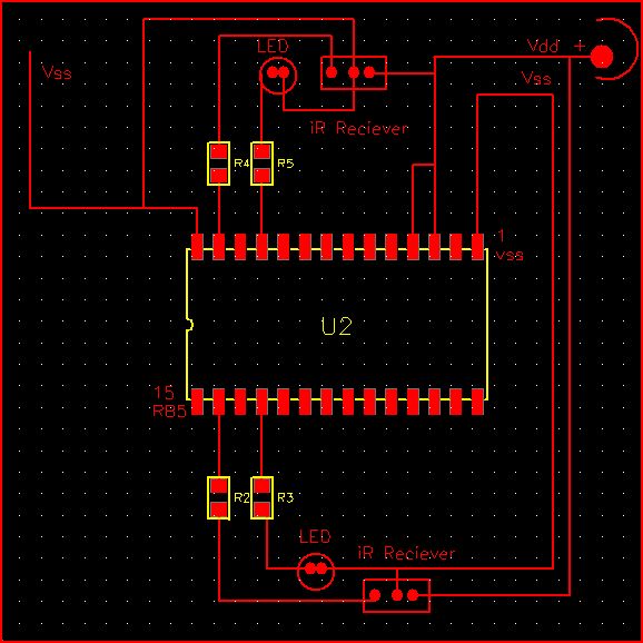
Before putting it on a PCB I would use the DIP version of the SX28 and wire it up on a breadboard first and then once I know it works then layout a board. The two versions of the SX28 are the same except for a slight difference in the pinout. Check the datasheet to verify before making the connections.
You haven't provided enough information for us to help. If you answer some questions that would make it easier to comment:
- What is the correct orientation of the chip? With the numbers you added it appears to be backwards.
- What are the value of the resistors you are going to use?
It looks like the trace coming off R5 doesn't actually connect to the LED. Also, what you attached is not a schematic, but a PCB design. Having the schematic would answer a lot of questions without people having to ask them, such as the values of the resistors.
Agreed. Even if you don't use their PCB service ExpressPCB (www.expresspcb.com) has a nice schematic tool that I use for documentation of circuits all the time.
Comments
You haven't provided enough information for us to help. If you answer some questions that would make it easier to comment:
- What is the correct orientation of the chip? With the numbers you added it appears to be backwards.
- What are the value of the resistors you are going to use?
- What type of IR modules are you going to use?
- Do you have any example code working?
It looks like the trace coming off R5 doesn't actually connect to the LED. Also, what you attached is not a schematic, but a PCB design. Having the schematic would answer a lot of questions without people having to ask them, such as the values of the resistors.
Thanks,
PeterM