Experiments for cub-scouts
Hi all,
I set up a couple of experiments for our cub-scout den to experiment with the Microcontrollers/Programming/Electronics.
After putting together a couple of OEM boards (previous Parallex offer), I connected up an LCD display (Jameco grab-bag prize) and some LED's (from another Jameco grab-bag)
attached to this post are the images of
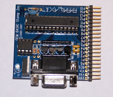
(1) One of the BS2sx OEM boards
(2) LCD shown working with BS2sx module plugged in
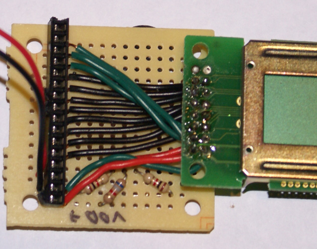
(3) Zoomed view of LCD from above
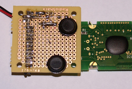
(4) Zoomed view of LCD from below
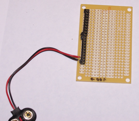
(5) A "blank" I've not done anything with yet. I did not have any SIL sockets around, so I got creative and split a DIL in half.
Post Edited (NetHog) : 3/3/2009 5:33:48 PM GMT


Comments
Again, demonstration view, top view and bottom view.
I will post schematics later, albeit they were very trivial.
The LCD was connected as follows:
P0-P7 = 8-bit data bus (you can use only 4 bits, but that's harder to explain to newcomers)
P8·= E
P9 = RW
P10 = RS
The resisters were chosen to get a reasonable contrast without having to purchase a new trimmer. If I had a trimmer at hand, I'd have used that instead! It was pretty much trial and error.
For the LED board,
P0 = Red-1 (traffic light 1)
P1 = Yellow-1
P2 = Green-1
P3 = Red-2 (traffic light 2)
P4 = Yellow-2
P5 = Green-2
P6 = Red-3 (ped crossing)
p4 = Green-3
Note that the comments are targetted at cub-scout / young scout·age-group (pre-teen to early teen).
I ended up using the LCD mostly as a demo, and concentrated on having the boys modifying the LED program. The LCD project had a fun quirk as, when connected via the debug cable, you can type text and make it appear on the LCD display.
You'll note·in earlier photo·that the LED's were not lit in a traffic-light pattern.·That's because one of the boys decided to make all the LED's light in sequence then turn off in sequence.
I'll post schematics tomorrow.
Note that JP1 in both circuits is for the BS2sx OEM board (see earlier photo).
Design note regarding driving LED's from BS2sx:
Max draw for 8 I/O pins is 60mA. If all LED's are lit, that's 7.5mA per LED.
Approx current for LED is (5-2)/470 = 6.4mA
Post Edited (NetHog) : 3/4/2009 5:31:25 AM GMT