

Controlling a LCD display, problems/questions on where to start
 Joms
Posts: 279
Joms
Posts: 279
I am fairly new to the propeller code, been through chapter 3 of the manual, starting my first project but have a few questions...
·
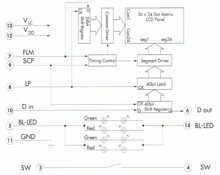
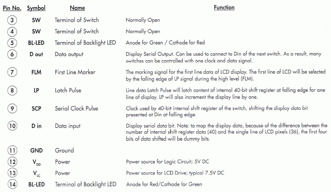
I am attempting to control an LCD display built into a push button surface that I asked about awhile back in a post.· I was able to find a spec sheet from the manufacturer that gives me a pin-out and a timing diagram.· Here’s that I am thinking, but where I am wrong can someone set me straight....
·
1.· I am trying to build this as its own object to be called upon by the main program, just like the TV_terminal function.
·
2.· Is there an easy way to line up the Serial Clock Pulse, Data out of the Propeller, Latch Pulse, and First Line Marker?
·
3.· I was trying to make the frequencies just like we used the toggle function in the tutorial, but I can only get one to put out the right frequency at a time.· (regarding the Serial Clock Pulse, Latch Pulse, and First Line Marker)
·
At this time I am not worrying about the backlight or button function, the goal is just to produce an letter, or work on the LCD display.· I am not asking someone to right this for me, but just point me in the right direction or 'get me going'.
·
When I get this Object completed I will be more then willing to share it, or post it in the object exchange, because I think these buttons are very, very neat to a lot of people, and many people would probably love them on their projects.
·
I have attached a few pictures of the datasheet.· I tried to post the whole sheet but it was too large.
THANKS!
·
I am attempting to control an LCD display built into a push button surface that I asked about awhile back in a post.· I was able to find a spec sheet from the manufacturer that gives me a pin-out and a timing diagram.· Here’s that I am thinking, but where I am wrong can someone set me straight....
·
1.· I am trying to build this as its own object to be called upon by the main program, just like the TV_terminal function.
·
2.· Is there an easy way to line up the Serial Clock Pulse, Data out of the Propeller, Latch Pulse, and First Line Marker?
·
3.· I was trying to make the frequencies just like we used the toggle function in the tutorial, but I can only get one to put out the right frequency at a time.· (regarding the Serial Clock Pulse, Latch Pulse, and First Line Marker)
·
At this time I am not worrying about the backlight or button function, the goal is just to produce an letter, or work on the LCD display.· I am not asking someone to right this for me, but just point me in the right direction or 'get me going'.
·
When I get this Object completed I will be more then willing to share it, or post it in the object exchange, because I think these buttons are very, very neat to a lot of people, and many people would probably love them on their projects.
·
I have attached a few pictures of the datasheet.· I tried to post the whole sheet but it was too large.
THANKS!
743 x 591 - 41K
1066 x 621 - 84K
895 x 443 - 36K
Comments
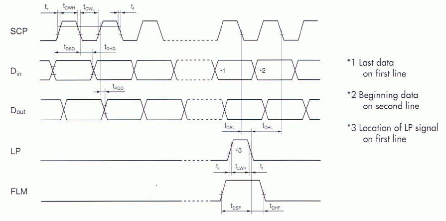
You don't want to line up the pulses, what is most important is that everything happens on the falling edge of the clock pulse. This type of protocol is common to many devices. What you need to do is set up the data first (i.e. hi or low on Din, LP and / or FLM ) then toggle the clock line (SCP) hi then low. That is the basic mechanics, you will need to make sure that the data setup time is met ( tDSD ) before the falling edge of the clock, and that you hold the data the appropriate time ( tDHD ) after the falling edge of the clock. The timing diagaram shows a regular clock pulse, but that is not important all activity is centered around the falling edge of the clock pulse ... whenever that may be, it does not have to be at the regular intervals the timing diagram may imply.
Here is a small chunk (incomplete) of pseudo code that shows you how to clock in 1 bit of data.
    repeat
        outa[noparse][[/noparse]Din] := currentBit    'set data hi or low
        waitcnt( tDSD + cnt )      'wait data set up time
        outa[noparse][[/noparse]SCP] := 1             'set SCP high
        waitcnt( tCWH + cnt )      'wait at least minimum clock hi time
        outa[noparse][[/noparse]SCP] := 0             'set SCP low
        waitcnt( tDHD + cnt )      'wait data hold time time

        currentBit := getNextBit   'get the next bit to transmit and repeat
The device will need 24 clockings of 40 bits of data to display a full screen. The LP pulse latches in the current line (40 bits per line) and increments the line counter to be ready to get the next line clocked in. The FLM pulse resets the line counter back to the first line. What you are doing is clocking in a 36 x 24 bitmap with 4 dummy bits at the beginning of each row (line) ... thus the 40 bits, not 36 as per the display. You can ignore Dout unless you want to daisy chain another device.
If this is your first go at hardware interfacing you will be busy! Good luck
-tellurian (Allen)
▔▔▔▔▔▔▔▔▔▔▔▔▔▔▔▔▔▔▔▔▔▔▔▔
Timothy D. Swieter, E.I.
www.brilldea.com - Prop Blade, LED Painter, RGB LEDs, uOLED-IOC, eProto for SunSPOT, BitScope
www.tdswieter.com
Tullurian - Your code example was a GREAT start for me! I semi understand how the code works as well as have a fairly good understanding of what the button is trying to accept for data. I am now just getting to the point of·writing the latch-pulse code segment. Is there any way to input the data other then making a variable number that will represent each pixel? What I mean, is can I utilize and of the pre-made characters in the chips memory?
Mr. Swieter - The device is a NKK brand smart switch that has a small LCD display built into the push button. The model is a IS15F2G2NP4, basically a common black/white LCD, single red/green LED backlight. What I am trying to do is just make a SPIN application that will run the button's LCD display and allow another application to control this file, the same way the TV_terminal function works. Eventually I would like to take the data out of this button and run it to the data in of another button, and so on down the line, up to 5 buttons total. If you happen to have some code already made that you would be willing to share that would be awesome, but otherwise, I am off to blaze a new trail of code.
Hi Joms,
The NKK "Smartswitch". I programmed that device a few years ago (I looked around for source code, but it is long gone, sorry). There is no on-board ROM on the device, it has no built in character set (no built in anything), it is just a raw LCD driver. You can read the characters out of the Propeller ROM but I think they may be too big for you, you will need to create your own character set.
see
https://www.nkksmartswitch.com/media/pdf/ApplicationNotes.pdf
http://www.nkksmartswitch.com/Uploads/DrivingSSPart1and2.pdf
If you root around the nkksmartswitch site your may find code samples ... or a more thorough hunt (than I did) on the web for smartswitch. Circuit cellar has a complete design and code using a Cypress PSOC microcontroller (very cool device) available for purchase (dunno how much $$, but then the device is not really that daunting you can do it yourself).
http://www.circellar.com/library/print/0702/kagan144/index.htm
-tellurian (Allen)
I read through both of those PDF's.· I am finding the one from NKK very useful.· I have attached the code I have so far...
Haveing a few problems...· I am trying to write this code in very small steps to see what works and what doesn't.· So far the code should continually pulse the clock pin, and every 40 pulses on the clock pin it should pulse the Latch pin.· This is where where the problem is.· I can't seem to even make it pulse the clock pin so I am assuming I am doing something major wrong with the code.· If anyone sees something that doesn't make any sense, please point it out...
Second...· What is the best way to go about inputing the data to the programming?· Is there a way I can create a 'lookup' type table, so everytime I call for a symbol on the display I can just point it twards the table?
Any ideas?
Hi Joms,
From your code it is not clear if you are calling it from another spin program. If you are using it as your main program what will happen is that the Start procedure will be called will run to completion and just end. Main will never actually run unless you call it from Start or better yet merge it into Start (i.e. make main just a continuation of Start ). Once you have done this you will see the clock and other lines toggle.
Regarding data input, set up a an array in a VAR section declared as byte bitmap[noparse][[/noparse]120]. This would be accessed 5 bytes per line (i.e. 5 bytes = 40 bits) for 24 lines. Your repeat loop would just continually cycle through those bits. Whatever bit pattern you place there will end up on your LCD. If this routine is on a separate COG you can just let it run blindly, cycling through the bitmap and another calling cog can update the bitmap with new data to display as required.
Timing and sequencing is critical of course, I will leave that up to you to work it out. With the PDFs and Spec sheet you will have enough info to work it out (with a little hair pulling here and there maybe). Check out Fig 2a in the Circuit Cellar PDF (DrivingSSPart1and2.pdf) it has some key timing information.
-tellurian
Incidentally, the NKK SmartSwitch is a bad name. It is not smart at all. It was all there was for 5 or 6 years. There are newer (and cheaper) switches that are identical but have built in controllers and their own RAM so all you have to do is send commands and bitmaps to display, you do not have to turn your microcontroller into an LCD driver for the NKK "DumbSwitch"
http://www.sparkfun.com/commerce/product_info.php?products_id=8492
It is virtually the same switch but with all of the control logic and memory in it. You just issue it serial commands as if it were a static device. You do not have to continually refresh the LCD on a regular basis like NKK's so-called ( ahem ) "SmartSwitch". If it isn't too late you may want to consider using those. If those "Graphic Buttons" were available 6 years ago I would probably have used them.
-tellurian