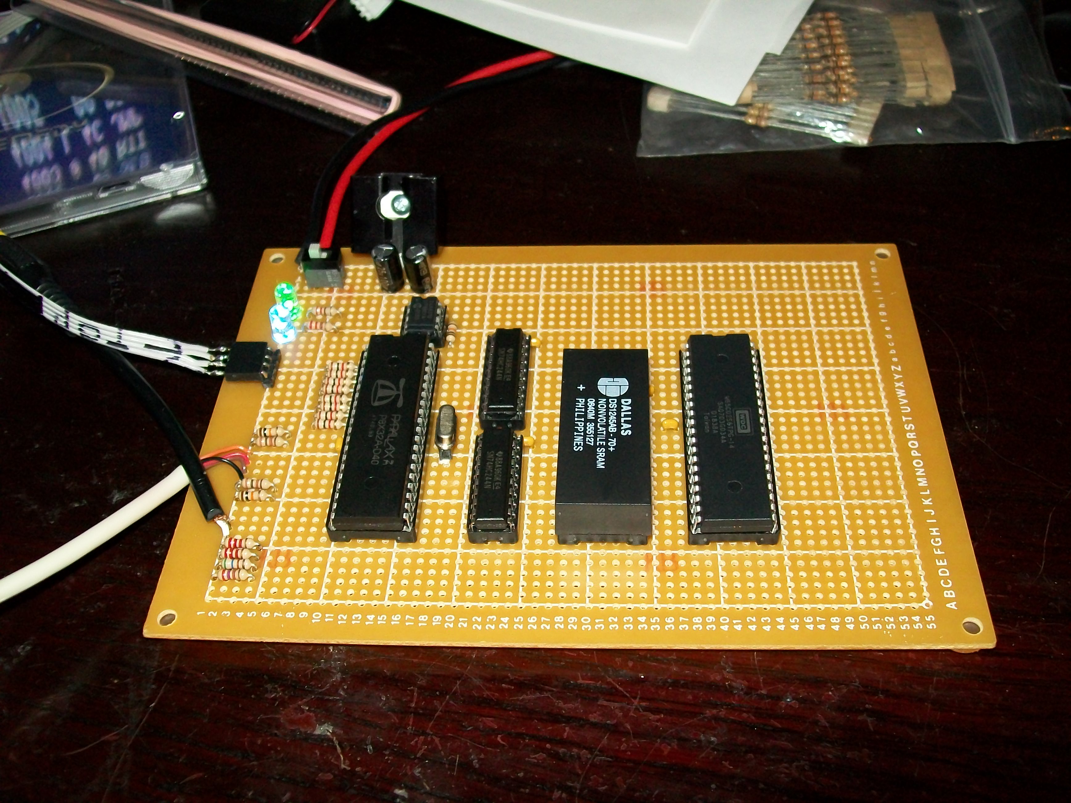
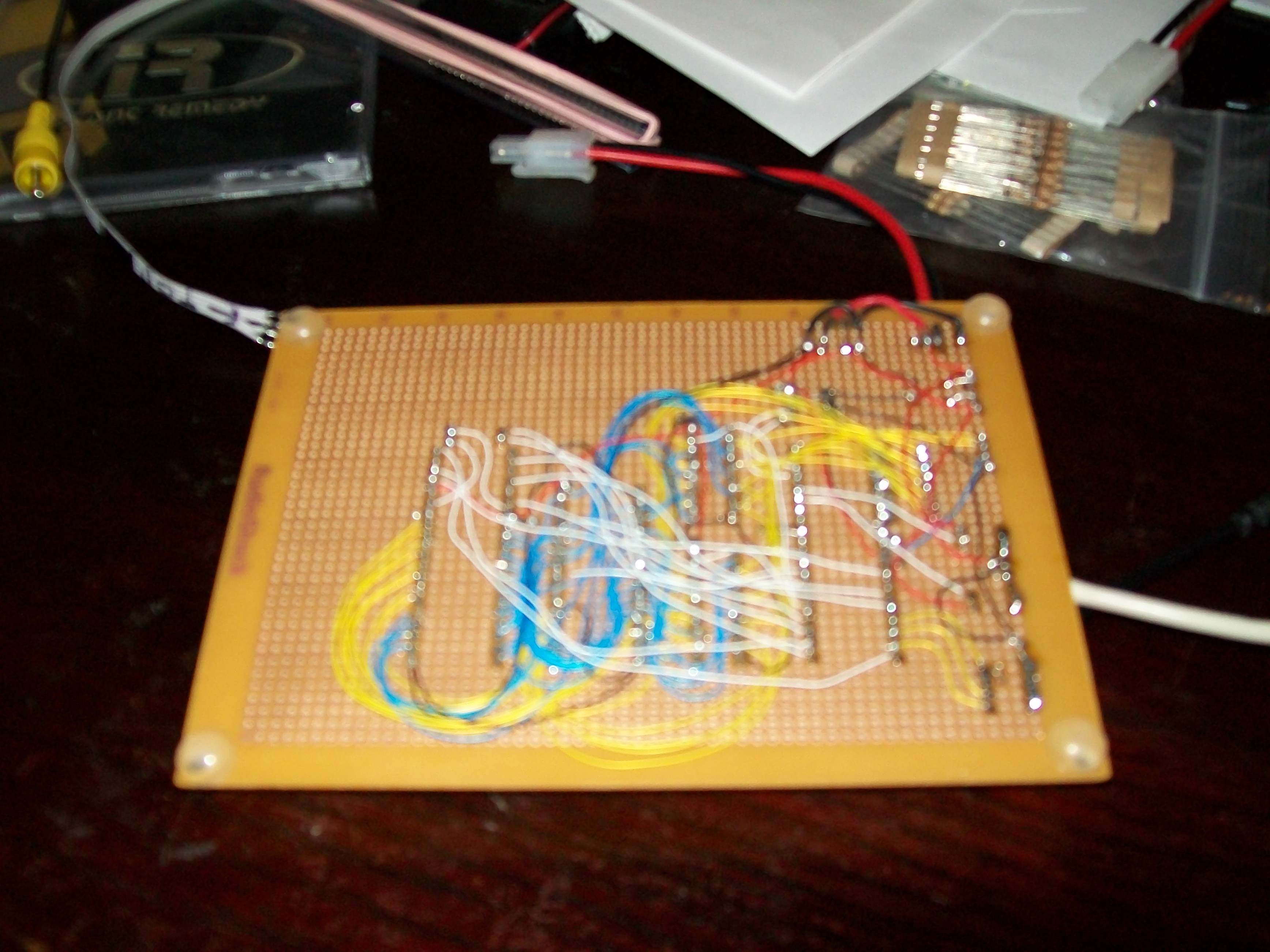
Dennis Ferrons 6502 board...
Howdy...
I'm trying to re-create the 6502 board that Dennis Ferron made for the Prop design contest...
www.parallax.com/tabid/708/Default.aspx
I thought I got it correct but the board just doesn't work...
The Demo Block Transfer just shows $00 on all addresses and 256 errors.
The Debug demo shows the 6502 address all over the place, kind of random.
The Lower 74HC244 is wired to the Low Byte addresses,
Pin 2 to address A0, 4-A1, 6-A2, 8-A3, 17-A4, 15-A5, 13-A6 and 11-A7.
Pin 18 to Propeller P0 over 1Kohm, 16-P1, 14-P2, 12-P3, 3-P4, 5-P5, 7-P6 and 9-P7.
Did I get this combination right ?
Upper 74HC244 is the same but with A8 to A15.
I could not find the SRAM in the project but I was able to get a free sample of DS1245AB-70.
www.maxim-ic.com/quick_view2.cfm/qv_pk/2664
It's wired according to the schematics, but A16 is pulled to ground.
I didn't have a 6502 so I used a WDC65C02.
www.westerndesigncenter.com/wdc/w65c02s-chip.cfm
Pin 36 (Bus Enable) is pulled high to +5V and Pin 1 (Vector Pull) is left floating since it's an output.
Besides that I've triple checked all the connections etc...
Just wonder if there is something obvious I forgot.
▔▔▔▔▔▔▔▔▔▔▔▔▔▔▔▔▔▔▔▔▔▔▔▔
Living on the planet Earth might be expensive but it includes a free trip around the sun every year...
Experience level:
[noparse][[/noparse] ] Let's connect the motor to pin 1, it's a 6V motor so it should be fine.
[noparse][[/noparse] ] OK, I got my resistors hooked up with the LEDs.
[noparse][[/noparse]X] I got the Motor hooked up with the H-bridge and the 555 is supplying the PWM.
[noparse][[/noparse] ] Now, if I can only program the BOE-BOT to interface with he Flux Capacitor.
[noparse][[/noparse] ] I dream in SX28 assembler...
/Bamse


Comments
Realized that the HC series might not work, switched to 74LS244 and added a few NOPs in the program to slow things down...
I got the debugger to work, however the Block Transfer demo still do not work...
▔▔▔▔▔▔▔▔▔▔▔▔▔▔▔▔▔▔▔▔▔▔▔▔
Living on the planet Earth might be expensive but it includes a free trip around the sun every year...
Experience level:
[noparse][[/noparse] ] Let's connect the motor to pin 1, it's a 6V motor so it should be fine.
[noparse][[/noparse] ] OK, I got my resistors hooked up with the LEDs.
[noparse][[/noparse]X] I got the Motor hooked up with the H-bridge and the 555 is supplying the PWM.
[noparse][[/noparse] ] Now, if I can only program the BOE-BOT to interface with he Flux Capacitor.
[noparse][[/noparse] ] I dream in SX28 assembler...
/Bamse
▔▔▔▔▔▔▔▔▔▔▔▔▔▔▔▔▔▔▔▔▔▔▔▔
http://www.propgfx.co.uk/forum/·home of the PropGFX Lite
·
I was looking up the specs for the DS1245 and found out that this chip is $40.
Not really practical since I'm thinking of making a PCB for this.
I have a couple of 62256 (32Kb chips for $3 each) and I want to replace the DS1245 with two of these in stead.
So I'm going to piggy back two of those in the existing socket and use a 74LS04 (NOT gate) to "decode" A15 for Chip Enable.
That will be tonights exercise...
▔▔▔▔▔▔▔▔▔▔▔▔▔▔▔▔▔▔▔▔▔▔▔▔
Living on the planet Earth might be expensive but it includes a free trip around the sun every year...
Experience level:
[noparse][[/noparse] ] Let's connect the motor to pin 1, it's a 6V motor so it should be fine.
[noparse][[/noparse] ] OK, I got my resistors hooked up with the LEDs.
[noparse][[/noparse]X] I got the Motor hooked up with the H-bridge and the 555 is supplying the PWM.
[noparse][[/noparse] ] Now, if I can only program the BOE-BOT to interface with he Flux Capacitor.
[noparse][[/noparse] ] I dream in SX28 assembler...
/Bamse
Seems like the 62256 works a lot better, both debugger and block transfer works...
However there are some errors on memory location $B000 and above, I think I burned part of one of the RAM chips...
Time to tear things apart and put two memory chips side by side...
▔▔▔▔▔▔▔▔▔▔▔▔▔▔▔▔▔▔▔▔▔▔▔▔
Living on the planet Earth might be expensive but it includes a free trip around the sun every year...
Experience level:
[noparse][[/noparse] ] Let's connect the motor to pin 1, it's a 6V motor so it should be fine.
[noparse][[/noparse] ] OK, I got my resistors hooked up with the LEDs.
[noparse][[/noparse]X] I got the Motor hooked up with the H-bridge and the 555 is supplying the PWM.
[noparse][[/noparse] ] Now, if I can only program the BOE-BOT to interface with he Flux Capacitor.
[noparse][[/noparse] ] I dream in SX28 assembler...
/Bamse
I would have thought the 74HC244 would have been fine. Are you sure you are using +5V on the 6502 section.
What clock speed is the prop outputting to the 6502? Try slowing this down to slow the 6502.
If you don't get anywhere I may be able to help further after the weekend.
▔▔▔▔▔▔▔▔▔▔▔▔▔▔▔▔▔▔▔▔▔▔▔▔
Links to other interesting threads:
· Home of the MultiBladeProps (SixBladeProp)
· Prop Tools under Development or Completed (Index)
· Emulators (Micros eg Altair, and Terminals eg VT100) - index
· Search the Propeller forums (via Google)
My cruising website is: ·www.bluemagic.biz
The 65C02 is feed by 5V and I think the Prop clocks it around 3.5 MHz.
I checked out Future Electronics and I'm going to order some of the AS6C1008 tomorrow.
Another idea I got is that the WDC65C02 does work at 3.3V and maybe I should just get everything running a 3.3V.
The 65C02 I have should work at 14MHz for 5V and 8MHz for 3.3V.
▔▔▔▔▔▔▔▔▔▔▔▔▔▔▔▔▔▔▔▔▔▔▔▔
Living on the planet Earth might be expensive but it includes a free trip around the sun every year...
Experience level:
[noparse][[/noparse] ] Let's connect the motor to pin 1, it's a 6V motor so it should be fine.
[noparse][[/noparse] ] OK, I got my resistors hooked up with the LEDs.
[noparse][[/noparse]X] I got the Motor hooked up with the H-bridge and the 555 is supplying the PWM.
[noparse][[/noparse] ] Now, if I can only program the BOE-BOT to interface with he Flux Capacitor.
[noparse][[/noparse] ] I dream in SX28 assembler...
/Bamse
At least the Data sheet for 74HC244 say 2.0 - 5.5 V.
I ordered a few of the 128 KB memory chips from Future Electronics, they run at 3.3V so I think I have all the components needed to convert to 3.3V...
Just to give you guys a hint about a future project, I ordered a couple of Z80s as well...
▔▔▔▔▔▔▔▔▔▔▔▔▔▔▔▔▔▔▔▔▔▔▔▔
Living on the planet Earth might be expensive but it includes a free trip around the sun every year...
Experience level:
[noparse][[/noparse] ] Let's connect the motor to pin 1, it's a 6V motor so it should be fine.
[noparse][[/noparse] ] OK, I got my resistors hooked up with the LEDs.
[noparse][[/noparse]X] I got the Motor hooked up with the H-bridge and the 555 is supplying the PWM.
[noparse][[/noparse] ] Now, if I can only program the BOE-BOT to interface with he Flux Capacitor.
[noparse][[/noparse] ] I dream in SX28 assembler...
/Bamse
▔▔▔▔▔▔▔▔▔▔▔▔▔▔▔▔▔▔▔▔▔▔▔▔
http://www.propgfx.co.uk/forum/·home of the PropGFX Lite
·