

Gadget Gangster Project board II (v.1)
 Nick McClick
Posts: 1,003
Nick McClick
Posts: 1,003
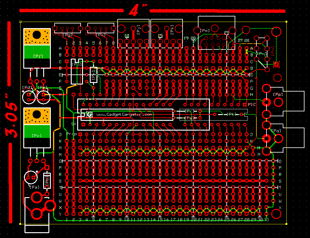
I've been working on a second project board (in addition to the board we already carry) and I'm looking for a little feedback - it's attached to this post.
The idea is to support either an SX or Propeller. It also supports 3.3 & 5v. I've added 2 mounts for vertical pots or a 3.5mm stereo headphone jack (either will fit). I rolled up a video DAC under the Propeller socket. I've also added mounts for a Nintendo controller connector.
I've got some extra space on the board. Any suggestions for additional connectors? I was thinking of a slide switch. SD cards would go on a breakout board. I like PS/2, but a lot of people don't have PS/2 keyboards anymore. What other connectors would be helpful?
Also, any feedback on the power setup would be helpful. I go back and forth on a diode, is it necessary? Anything else look wonky on the board?
Edit - I've attached V .2
Edit again - the attached image now reflects the most current / near final design
▔▔▔▔▔▔▔▔▔▔▔▔▔▔▔▔▔▔▔▔▔▔▔▔
Gadget Gangster - Share your Electronic Projects - Sign up as a Designer and get a free 4-pack of Project Boards!
Post Edited (Nick McClick) : 3/2/2009 9:22:59 PM GMT
1012 x 780 - 40K
Comments
why I think its one of the strongest appeals for your full board and your adapter boards.
Also, I'm not a huge fan of the 4-way connected pads. Perhaps two sets of 2-connected pads instead? It allows for more compact design on some aspects.
In addition to your new board, I'd suggest you make more breakout boards and sell them in singles/small kits. I'd buy some.
I do already have an RJ11 / 45 breakout. I'll do more breakouts, but I'd like to combine as much as possible to keep projects inexpensive. Also, breakout boards are a little tacky for kit builders.
I agree with the 4 row. It seems to take up a lot of space. I'm also thinking that most add on chips are going to be 300 mil.
I like DE-9 as much as the next man, but there haven't been any projects posted that use it. If you had to choose between nintendo connector & a DE-9, which would you prefer?
Any other connectors? MIDI? S-Video? BNC?
▔▔▔▔▔▔▔▔▔▔▔▔▔▔▔▔▔▔▔▔▔▔▔▔
Gadget Gangster - Share your Electronic Projects - Sign up as a Designer and get a free 4-pack of Project Boards!
I'd personally pick DB-9, but I'm not a Prop-user so ignore my opinion on that [noparse]:)[/noparse]
Have you thought about including a mini-usb connector? I wouldn't use it, but I'm sure it could come in handy if you have some spare room.
Mounting holes in the standard locations would be very helpful, as would any other mounting holes (particularly holes to hold your half-board on standoffs)
Large holes for larger gauge wire would be good too. I used the PS2 holes on my last project, but it wasn't very elegant.
Do the long rails need to be tied to the power supply? In some projects you may want to use exclusively 3.3 volts or exclusively 5.0 volts.
Are you using 1.0 amp regulators or the 3.0 amp? Personally, I'd prefer to have it designed for the 3.0 amp just in case I want to run a motor or something.
The top rail is tied into Vin. The rail below the chip is 'jumperable' to Vin or the second Regulator. The 3rd rail is open. Good article on xtal placement, I'll re-route the resonator for the SX. I think you could use a 3 amp power supply, but you'd probably want to use a heatsink. I'm not sure if the board would sink that much heat. Other points noted.
I'll probably add standoff holes, but I think that pin header / sockets are a better way to mesh boards (like the arduino shields - here). Having mounting holes is cool to attach your project to a boe-bot, though.
▔▔▔▔▔▔▔▔▔▔▔▔▔▔▔▔▔▔▔▔▔▔▔▔
Gadget Gangster - Share your Electronic Projects - Sign up as a Designer and get a free 4-pack of Project Boards!
Here's a vote to add it above the 3.5mm stereo headphone jack on the left.
The SD is easy to add using either an add-on board or just soldering the pins
directly to a few lines on the right side, so no issue there.
Looks like you've got a place to tap the 3v, but no place to tap into 5v.
(Am I missing it?)
All in all good direction! It solves a lot issue with the current design
and will certainly make Propeller design a LOT easier.
OBC
▔▔▔▔▔▔▔▔▔▔▔▔▔▔▔▔▔▔▔▔▔▔▔▔
New to the Propeller?
Check out: Protoboard Introduction , Propeller Cookbook 1.4 & Software Index
Updates to the Cookbook are now posted to: Propeller.warrantyvoid.us
Got an SD card connected? - PropDOS
This way your two full board designs could be used as motherboards with half-boards as add-ons.
This sounds extremely weird... but have you thought about having a single pin hole next to (and connected to) each standoff hole so you can easily connect grounds or supplies through
metal standoffs? It's an idea I've been toying with for quite some time.
Yeah, there's currently only one tie to the secondary regulator (the secondary regulator would be 3.3V if you were running an SX). I'll need to spread that out a little more. A bit of a pain with the current design; the nintendo connector needs +5; with an SX, it's fine. But with a prop, you'll have to run a jumper.
@ugha - That's a good idea; it comes down to cost, and a half board doesn't really cost much more than a breakout (at least at these quantities). Plus, a lot of breakout boards require additional circuits anyway, so giving the additional space necessary to set it up makes sense.
But the connectors between boards are pretty expensive (and the costs don't scale well). That's why I'm trying to add the most common connectors on the board.
I'm really hoping this board will help make it easy to do projects that get non-hobbyists excited. The current board works for small chips, but it's a pain with big DIP's. I know a lot of folks are more on the software side, so I'm hoping this helps them, too.
Once this board is in the bag, I think the next board will be an ATmega / ATmini / PIC board. Then probably breakout halfboards based on the kinds of projects people are posting.
OKAY! Back to work [noparse]:)[/noparse]
▔▔▔▔▔▔▔▔▔▔▔▔▔▔▔▔▔▔▔▔▔▔▔▔
Gadget Gangster - Share your Electronic Projects - Sign up as a Designer and get a free 4-pack of Project Boards!
Having the extra pads tied together isn't too bad. Just keep an exacto blade and utility knife on your bench. When prototyping or hacking ciruits I often end up using an blade to sever unneeded traces. Just make a cut at each pad and you can take the section of trace right off the board. It's a useful technique to master if you work on a lot of projects. If you just want to open it at a hole then just use a drill and usually you can take them out with a few twists by hand.
Robert
http://forums.parallax.com/showthread.php?p=788092
Added numbers to each of the part sections, so a designer can just say, put the RCA jack in part area [noparse][[/noparse]13]. Buffed up some of the rails for better amperage. Shrunk / moved via's so builders don't think they're through holes. Fixed the prop xtal. The SX resonator is a bit of a hack, but it works. I didn't add any more caps, but it's pretty trivial to add a few caps on the board, though. I also added support for PICaxe 08, 14, and 20. I'm pretty happy with that. Also, the bottom weave rail has easy hookups to either regulator or ground. I spent a lot of time just looking at the bottom of the board (green traces) trying to spot any confusing areas for a builder.
Still need to add a few more things (mounting holes, clean up the number row on top, add some large through holes, numbers on both sides of the board, etc). This board will have silkscreen & solder mask, too.
How's it looking?
▔▔▔▔▔▔▔▔▔▔▔▔▔▔▔▔▔▔▔▔▔▔▔▔
Gadget Gangster - Share your Electronic Projects - Sign up as a Designer and get a free 4-pack of Project Boards!
for easier placement of the resistors. (at least where the two are placed)
Nice power rails.
This looks like the perfect board to give someone who wants to assemble
their own Propeller.
OBC
▔▔▔▔▔▔▔▔▔▔▔▔▔▔▔▔▔▔▔▔▔▔▔▔
New to the Propeller?
Check out: Protoboard Introduction , Propeller Cookbook 1.4 & Software Index
Updates to the Cookbook are now posted to: Propeller.warrantyvoid.us
Got an SD card connected? - PropDOS
Once you get it produced, I think it would be very helpful to have pictures of each of the possible setups (Prop, SX, PICs) and what goes where. It's very densely packed...
What are [noparse][[/noparse]15] and [noparse][[/noparse]16]?
I must say that I don't really like the weaving on the power rails. It looks cool, but I think it would be a pain to use. For example, on my current project, the half the EEPROM sits on the ground rail (since one side is all ground), and that saved several connections. Granted, you don't need to setup an EEPROM for this, but the principle applies. In addition, for compact designs with repetitive parts, the builder would have to dictate something like: "for parts on even number columns, attach to row M. For odd columns, attach to row N." While certainly possible, it's a hassle.
Will the regulators have heat sinks?
If you are going to provide part outlines, the game controller at [noparse][[/noparse]12] needs one.
Is that a reverse hookup protection diode at 4?
Very nice board! I'm excited...
Post Edited (SRLM) : 2/26/2009 4:25:20 PM GMT
I'm going to more carefully scrutinize some of the more common IC's, but I suspect it will be rare that half of the pin's on a dip all need to be grounded. You could also connect both rails to ground, that way you wouldn't have that problem. You'll note the board is already setup for the EEPROM.
The more common problem is that many IC's have VDD & VSS right next to each other. The weave supports that more easily. It also allows you to connect VSS or VDD with lead trimmings, instead of using the tiny red jumper.
The idea for heatsinks is for the builder to tack down (or screw) the tab to the board. Those big red patches are unmasked solder areas.
I'll take photos and do a really nice howto for putting each component on the board, including each of the chips. That way, you likely won't need to do anything for the howto guide. As an example, say your project is a midi-to-audio converter; You'd just grab three parts of the howto guide - (1) setting up the propeller, (2) setting up the RCA jack, and (3) setting up the MIDI port. You wouldn't need to do any photos at all.
Let me also look more closely on the mini din. I think 95% of the usage will be PS/2, so I'll make sure it's set up for that. I should also bring the 'non-chip' VDD rail up from the Nintendo connector near to the PS/2. If you plan on using a Prop + keyboard, you'll need that +5v.
Next steps;
▔▔▔▔▔▔▔▔▔▔▔▔▔▔▔▔▔▔▔▔▔▔▔▔
Gadget Gangster - Share your Electronic Projects - Sign up as a Designer and get a free 4-pack of Project Boards!
1 - SX with audio out and a resonator
2 - Prop with Nintendo, PS/2, xtal, and video out
3 - A Picaxe 08m with... not really anything.
Not a 100% setup (the prop would still need a jumper for the 5v and a few jumpers and resistors for the PS/2 and game controller), but just an idea of fit. Anyway, I should get pre-production boards back in a few days and I'll mail them out shortly after.
Anyway - a few photos attached.
▔▔▔▔▔▔▔▔▔▔▔▔▔▔▔▔▔▔▔▔▔▔▔▔
Gadget Gangster - Share your Electronic Projects - Sign up as a Designer and get a free 4-pack of Project Boards!
That looks like the perfect Proputer, a great starting point for ANY Propeller project!
I'd like to purchase three of these boards w/power regulation when they arrive!
OBC
▔▔▔▔▔▔▔▔▔▔▔▔▔▔▔▔▔▔▔▔▔▔▔▔
New to the Propeller?
Check out: Protoboard Introduction , Propeller Cookbook 1.4 & Software Index
Updates to the Cookbook are now posted to: Propeller.warrantyvoid.us
Got an SD card connected? - PropDOS
I've also added the relevant connectors to the inventory.
The potentiometers: 10K, 50K, and 5K. I think a few more Pots will fit those mounts, I'll keep looking around.
The Stereo Jack
The Mini-DIN's 5p, 6p, and 8p. 6pin = PS/2. There wasn't enough room for a full DIN mount, but I'll add a min-din to regular din cable for use with MIDI projects.
The slide switch
And the Voltage Regulators 5v, and 3.3v
▔▔▔▔▔▔▔▔▔▔▔▔▔▔▔▔▔▔▔▔▔▔▔▔
Gadget Gangster - Share your Electronic Projects - Sign up as a Designer and get a free 4-pack of Project Boards!
Should you consider selling some of the boards, I would like to purchase at least 3 boards (i will take care of the rest of the parts). I can send you the cheque (or PayPal) and includes shipping charges (I am from Western Canada).
I have some projects on hold as I am still waiting for the "other" board from Phildapill. I could use either boards if I get lucky to recieve them soon....
Thanks
Rizthomas
@srlm - only two mounting holes on the right. Ideally, I would have put 6 more mounting holes, 2 on the left edge, 2 on the middle top and 2 on the middle bottom, but there just wasn't enough room on the board. Bottom holes would have wiped out 600 mil DIP's and shifted the power jack right. Mounting holes on the top would have wiped out the pots / stereo jacks, and required the voltage regulator to shift right. Looking at the projects so far, there seems to be more requests for pots and switches, less for mounting.
It's definitely a compromise, but the good news is that the current boards aren't going anywhere, and they have better support for mounting. The new boards can still be mounted, but the left side should probably rest on bosses.
▔▔▔▔▔▔▔▔▔▔▔▔▔▔▔▔▔▔▔▔▔▔▔▔
Gadget Gangster - Share your Electronic Projects - Sign up as a Designer and get a free 4-pack of Project Boards!
The bottom regulator is connected to VDD and the top regulator. So, if you wanted to add a 5V regulator with a 3.3v chip, the 3v regulator would need to feed a 5v regulator. Obviously a no go. It works fine if you're running a 5v chip, or you just need 3.3v.
I've re-routed the regulators to run parallel. This way, you can use 3v, 5v, or two 3v's or 5v regulators. Everything fits well - I setup a Prop to run the graphics demo and everything looked fine.
I'm going to send out these prototype boards tonight, let designers kick them around for a few days and provide any feedback, roll in any changes and send them over to the board house.
Attached is a photo, note there's no Silkscreen / soldermask. The production boards will have black soldermask & white silkscreen.
▔▔▔▔▔▔▔▔▔▔▔▔▔▔▔▔▔▔▔▔▔▔▔▔
Gadget Gangster - Share your Electronic Projects - Sign up as a Designer and get a free 4-pack of Project Boards!
1 - The nintendo connector now routes to Vdd. This way, you can send 5v to the PS/2 and 3v to the nintendo connector. The benefit being you don't need any series resistors to interface with the controller.
2 - Added a second set of holes for using a larger cap at [noparse][[/noparse]Pa].
3 - I split D3 and E3. If you're using a resonator with an SX, you'll need to jump them. But allows you to do in-system programming if you're using a propeller.
4 - Obviously, the Voltage regulators have been fixed. Now they're running in parallel. You can use 2x 5v regulators, 2x 3v regulators or a mix.
5 - the SX's RTCC now runs down to J3, so you can connect to that, if you'd like.
I stayed up late last night trying to cram the PICaxe X series and Atmega. I got it to work, but it was messy, so I've decided to do those on another board. About 3 hours of routing wasted, but I'd rather carry two boards that are easy to develop with than save a bit of money and just stock one board that's a pain.
I was also thinking that clear soldermask might be better. That way you can see all the traces and easily see how everything is connected. Personally, I think the silkscreen looks a lot cleaner, too.
Anyway - Designers should get their prototype boards in the mail shortly. If you have any feedback, want a change, think something is dumb on the board, just shoot me an email / pm / whatever, and see if I can't fix it. I'll wait until Wednesday (March 11th) before forwarding the design on to production.
▔▔▔▔▔▔▔▔▔▔▔▔▔▔▔▔▔▔▔▔▔▔▔▔
Gadget Gangster - Share your Electronic Projects - Sign up as a Designer and get a free 4-pack of Project Boards!
Are the two holes by M and N by [noparse][[/noparse]PQ] necessary? From the image, it just looks messy around there. Personal preference would have them removed.
The three white lines at E, O, and S: are these meant to help builders quickly locate important rows? If so, it looks like there are three different 'types' of rows that they highlight: alternating +- rails, blank pads, and + or - rail. I'd suggest that C, O, and T are better placements for the rows: they're all blank pads where designers are most likely to put things.
An aesthetic suggestion: The nintendo connector outline is the only outline that appears to be 'connect the dots'. All the other outlines reference the actual shape of the connector, although it appears that there is some fluctuation about having the outline go through a hole or beside a hole. Personally, I like around the holes better than through the holes where the actual components would do so.
By the [noparse][[/noparse]PA] capacitor label, there is a weird'\' and '|' combination. Does that mean something? Also in that area is an extra pair of holes matching those for the capacitor. Do those mean something?
As a note, you may want to position your big label "boss board" with the Gadget Gangster underneath that so that, with whatever sockets you use, it is most visible.
I'm glad you got the big holes in near the top of the board, but a row number would be beneficial. What comes before A? ZZ? Also, a column 32 could be useful.
No ground plane for the crystals? Oh well, can't have everything...
What goes in [noparse][[/noparse]PW]? I thought it was an EEPROM, but the outline doesn't fit.
A couple of mounting holes could fit underneath the central chip area. I'm heading towards a project where the board will be mounted on a single beam. I was just going to do it diagonally, but square would be more elegant.
Don't take these comments to critical. I'm quite looking forward to seeing and working with the completed board, whatever it's form ends up being.
The M & N holes next to [noparse][[/noparse]Pq] are necessary to allow the designer to connect either of the rails to ground.
Yeah, the lines are meant to assist in finding areas (like a grid on a map). Agreed on COT. They're not really there to highlight rails (I had that on a previous version of the silkscreen, but I think a clear soldermask will make finding the rails very easy).
The Nintendo connector is pretty big, drawing a silkscreen along the outside might look a little messy
The extra set of holes for the cap are there if the designer would like to use a larger cap. Maybe a builder would get confused by it?
I had the same question regarding what comes before A. That first set of holes was mostly for mounting connectors, but they'd work just fine if you wanted to use them for thick wires. I'll shift up the lettering.
The \| was a bracket for pointing to where the component should go. I thought I had removed them all.
No ground plane, but I let a prop run the graphics demo for a day and a half and no problems. It's much better than the previous routing for the xtal [noparse]:)[/noparse]
PW is an eeprom.
I could do two more mounting holes straight under the chip. It looks big on the monitor, but the board is pretty small and light - it doesn't take a lot to secure it.
▔▔▔▔▔▔▔▔▔▔▔▔▔▔▔▔▔▔▔▔▔▔▔▔
Gadget Gangster - Share your Electronic Projects - Sign up as a Designer and get a free 4-pack of Project Boards!
It seems awfully cruel to only have one controller port... I imagine you might use the controller to control servos or maybe an LED sequencer, or drive your roomba, send MIDI commands, or whatever. I also don't know how many projects will be multiplayer videogames, but multiplayer tetris might have been even cooler.
▔▔▔▔▔▔▔▔▔▔▔▔▔▔▔▔▔▔▔▔▔▔▔▔
Gadget Gangster - Share your Electronic Projects - Sign up as a Designer and get a free 4-pack of Project Boards!
Emailed you this morning regarding the 5v issue. Do you want to use this thread for
designer review Q&A on this board? I'm looking forward to finally getting some time
to play tonight after I get off work.
OBC
▔▔▔▔▔▔▔▔▔▔▔▔▔▔▔▔▔▔▔▔▔▔▔▔
New to the Propeller?
Check out: Protoboard Introduction , Propeller Cookbook 1.4 & Software Index
Updates to the Cookbook are now posted to: Propeller.warrantyvoid.us
Got an SD card connected? - PropDOS
▔▔▔▔▔▔▔▔▔▔▔▔▔▔▔▔▔▔▔▔▔▔▔▔
Gadget Gangster - Share your Electronic Projects - Sign up as a Designer and get a free 4-pack of Project Boards!
Features
Connectors
The best benefit - projects designed on the board can be published and sold on Gadget Gangster! This board is a big step up from our first set of project boards and I think you'll find them much easier to design and build cool projects with. I owe a few designers prototype boards, I'll send those out on Thursday.
If you've signed up as a designer, I'll drop you a note when the new boards are available (should be around the end of the month) and you'll be able to get them at a discounted price. I'll also post a note on the forums.
Nick
▔▔▔▔▔▔▔▔▔▔▔▔▔▔▔▔▔▔▔▔▔▔▔▔
Gadget Gangster - Share your Electronic Projects - Sign up as a Designer and get a free 4-pack of Project Boards!