

BS2 PCB Drill
 Propability
Posts: 142
Propability
Posts: 142
· Hi
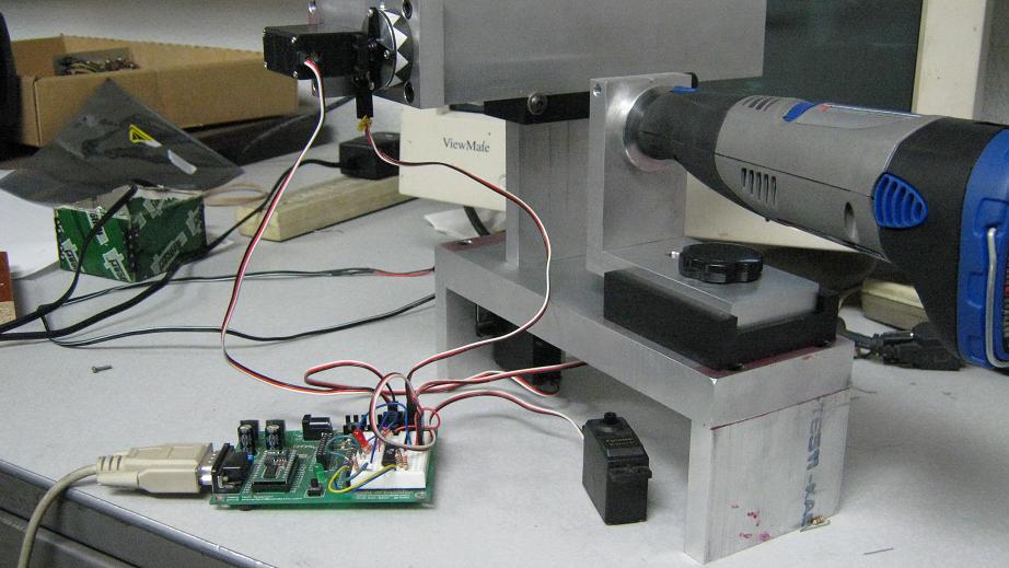
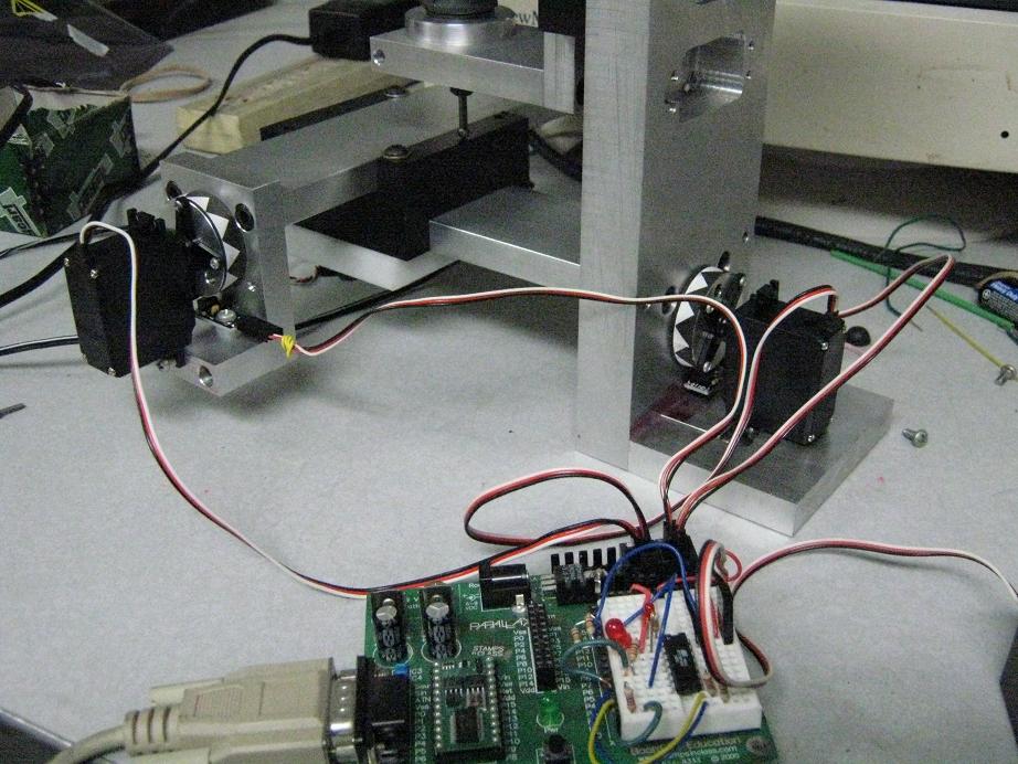
Just thought I would share a few pics of what I have been playing around with. What I wanted to do was a minimal setup using Parallax products as much as possible.
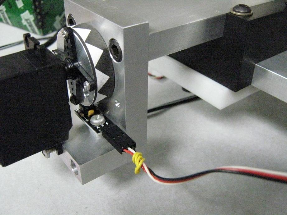
For some reason the QTI sensors have the power for the device on the white wire and the signal on the red wire. So in essence you could not plug them into the servo headers. What I did was reverse the red and white wires on one end of the cable and wrapped a yellow (caution) wire on that end and so I was able to plug them into the headers.
I also have a 10K going from another pin into the pin for the sensor so that way I can use RCTIME when I'm moving in small increments and then when I want to move fast I turn on the pin with the 10K and now I can just use IN to read the state of the pin.
The chip on the breadboard is a tiny24 that I have been playing with. For right now it just blinks an led from a program that I loaded into it with that setup on the breadboard using a very simple BS2 program.
Just thought I would share a few pics of what I have been playing around with. What I wanted to do was a minimal setup using Parallax products as much as possible.
For some reason the QTI sensors have the power for the device on the white wire and the signal on the red wire. So in essence you could not plug them into the servo headers. What I did was reverse the red and white wires on one end of the cable and wrapped a yellow (caution) wire on that end and so I was able to plug them into the headers.
I also have a 10K going from another pin into the pin for the sensor so that way I can use RCTIME when I'm moving in small increments and then when I want to move fast I turn on the pin with the 10K and now I can just use IN to read the state of the pin.
The chip on the breadboard is a tiny24 that I have been playing with. For right now it just blinks an led from a program that I loaded into it with that setup on the breadboard using a very simple BS2 program.

Comments
Who and where are you getting the machined parts from
I thought of making something like this before
So I will keep my eye on this post to see what you come up with····
▔▔▔▔▔▔▔▔▔▔▔▔▔▔▔▔▔▔▔▔▔▔▔▔
··Thanks for any·
·
·
·
·
Sam