Wireless Musical Keyboard
Wireless Musical Keyboard
This activity demonstrates how to design and play a simple wireless musical keyboard using 3 pushbuttons, a piezospeaker and a wireless RF Transmitter and Receiver module.· Two HomeWork boards will be used: one outfitted with three pushbuttons and an RF Transmitter module, and the other with a piezospeaker and an RF Receiver module.· When complete, you will be able to press buttons on one board and a tone will play through the piezospeaker on the other.
·
Download zipped video clip· – RfBasics_Twinkle.wmv
Getting Started
If you are new to the BASIC Stamp microcontroller or to programming, it would be a good idea to review the following before beginning:
·
√······· Complete the following chapters in What’s a Microcontroller:
o······· Chapter 1 (Getting Started with the BASIC Stamp)
o······· Chapter 3, Activities 2 & 3 (Pushbutton Control)
o······· Chapter 8, first half of activity 5 (SELECT…CASE Statements)
√······· Download the 433 MHz Parallax RF Receiver Manual and the 433 MHz Parallax RF Transmitter Manual and read them for tips on using these RF modules.
What is RF?
Some of the most exciting BASIC Stamp applications can be accomplished with Radio Frequency (RF) transmitters and receivers.· The best part is that RF communication is all around!· Every time you listen to the radio, use a cell phone, or watch television RF transceivers are at work.· RF communication uses radio waves instead of wires for exchanging signals, which is where the name “wireless communication” comes from.· RF modules use frequencies (measured in Hz) to distinguish different radio signals, so in order for RF modules to “talk”, they must be operating on the same frequency.· This activity uses the 433 MHz Parallax RF Transmitter and Receiver modules.· The transmitter sends signals using radio waves that oscillate at 433 MHz, and the receiver is tuned to the 433 MHz frequency, so it receives the signals.
Inside Wired Serial Communication
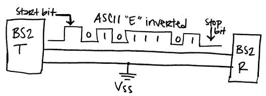
Since RF modules replace the wires devices would otherwise need to exchange information, let’s first take a look at how BASIC Stamp modules would exchange information if they were connected by wires.· BASIC Stamp modules (and a myriad of other digital devices) exchange information using serial communication.· For example, a BASIC Stamp sending the character “E” to another BASIC Stamp could use the command SEROUT TxPin, 16470, [noparse][[/noparse]“E”].· You can look up the SEROUT command in the BASIC Stamp Manual or the BASIC Stamp Editor’s help feature.· One of the thing’s you’ll find is a table that tells you when the SEROUT command’s Baudmode argument is set to 16470, it means that 8-bit data is sent inverted at a baud rate of 2400 bits/second.· Figure 1 shows an example of this exchange.· Since the baud rate is 2400 bits/second, each high/low signal has to last for 1/2400 of a second.· Inverted means that every binary 1 is transmitted as a 0, and vice-versa, and 8-bit means that each message has a byte’s worth of information (8 bits).
·
Figure 1 – Serial Transmission between Two Connected BASIC Stamps

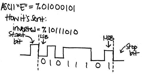
The ASCII value for the character “E” is 69, which is %01000101 in binary.· So why does it appear that the data is transmitted as %101011101?· The answer is for two reasons.· First, the SEROUT command is sending “inverted” data, and second, serial communication always sends its values least significant bit (LSB) first.
·
········· Inverted changes all the 1 bits to 0, and all the 0 bits to 1.· In the case of our ASCII value, it transforms %01000101 to %10111010.
········· Least significant bit first sends the rightmost digit first, followed by the second digit from the right, and so on.· That’s why the diagram shows all the digits backwards, as %01011101.
·
A serial message also has a start and stop bit, shown in Figure 2. ·At a baud rate of 2400 bits per second (inverted), the start bit is a high signal that lasts 1/2400 of a second, and it signals that 8 more 1/2400 of a second bits are on their way.· The stop bit is the minimum time before the transmitter is allowed to send another byte.· The BASIC Stamp uses 1 stop bit, which at 2400 bits/second means that the transmitter has to wait at least 1/2400 of a second before sending the next byte.
·
Figure 2 – How Data is Serially Transmitted
 ·
·
Inside Wireless Serial Communication
So we’ve covered transmitting serial data when two BASIC Stamp modules are connected.· What if we want them to transmit the data wirelessly, like we will in the following activity?· Does the theory change completely?· Not at all.· In fact, you can simply replace the wire with an RF transmitter and receiver, and the two BASIC Stamp modules can still exchange data as though they were using a wire.· Figure 3 shows how this works.· The only difference is that the transmitter gets data from the BASIC Stamp and sends it out through an antenna and into the air via radio waves, and the receiver module demodulates the radio signals back to wired serial signals and transmits them to the receiving BASIC Stamp.·
Figure 3 – Wireless Serial Transmission between Two BASIC Stamps
·
Schematics and Building the Circuits
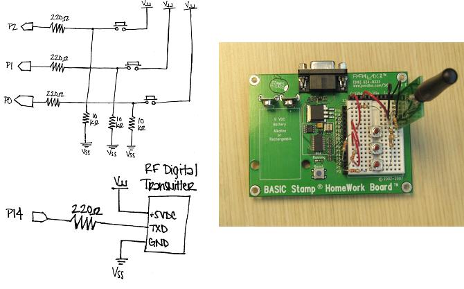
Figure 1 shows a schematic and wiring diagram for the RF transmitter board, and Figure 4 shows the schematic and wiring diagram for the RF receiver board.
·
√····Build the circuit shown in Figure 4 on one BASIC Stamp HomeWork Board (or Board of Education).
√····Build the circuit shown in Figure 5 on the other BASIC Stamp HomeWork Board (or Board of Education).
·
Figure 4 – Transmitter Board Schematic and Wiring

·Figure 5 – Receiver Board Schematic and Wiring

Program Listing – MultiButtonTx.bs2
√······· Enter and run MultiButtonTx.bs2 into your Transmittter board.
√······· Disconnect your programming cable from your tilt controller, but leave the battery (or DC supply) connected so the program keeps running.
√······· Move on to MultiButtonRx.bs2
·
Program Listing – MultiButtonRx.bs2
√······· Enter and run MultiButtonRx.bs2 in your Reciever board.
√······· Verify that when you push each of the pushbuttons on your Transmitter board, a tone plays on your Receiver board.
√······· If necessary, troubleshoot the circuit connections and/or code.
√······· Once each button plays a different note, you can play the first seven notes of “Twinkle, Twinkle Little Star” by pressing the first pushbutton twice, the second twice, the third twice, and the second once.
How it Works
MultiButtonTx.bs2
The program MultiButtonTx.bs2 utilizes the SEROUT command to transmit the states of the pushbuttons to the receiver board.· The INA argument is what’s called the “Nibble Name” which monitors the states of all devices connected to pins 0-3.· Recall that the command DEBUG ? IN3 prints “IN3 = 1” or “IN3 = 0” in the Debug Terminal depending on whether the pushbutton is pressed.· So when the command INA is called, it’s really the same as calling IN0, IN1, IN2, IN3. ·Then, when SEROUT TxPin, Baud, [noparse][[/noparse]PbStates] is called; it then sends the state of each pushbutton connected to P0, P1, P2, and P3 to the Parallax 433 MHz RF Receiver.
MultiButtonRx.bs2
The program MultiButtonRx.bs2 utilizes the SEROUT command to receive the states of the pushbuttons from the transmitter board.· However, it’s also a bit more complicated, since once the states are received, the program then has to decide what to do.· In order to sort each pushbutton state, the program uses a SELECT…CASE command.· Once SELECT PbStates is called, the received values of each pushbutton state are loaded into RAM as a byte.· However, there are four states that are received.·
·
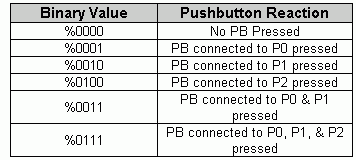
So how does the BASIC Stamp 2 store these values?· The simplest way to analyze how this is done is to read each byte in binary.· Since PbStates was defined as a Byte, there are four “spots” for the state of each pushbutton.· Remember, binary only stores values as 0’s or 1’s, and 0 is usually denoted as low and 1 as high.· So if we assign each “spot” to one pushbutton, the CASE command can be used to execute subroutines based on PbStates’s binary value.· The table below shows examples of how the BASIC Stamp will read each pushbutton state based on the binary value it has received. Our program is checking the states of the first three pushbuttons, but the INA command can check the first four pins, if desired.
·

·
So, by knowing the binary equivalent of each pushbutton being pressed; the CASE command can be used to compare each binary condition to PbStates and execute a subroutine based on that value.· In this program, depending on which pushbutton is pressed, a different note will play.
_____________________________________________________________________________
·
Copyright (c) 2009·by Parallax Inc - all rights reserved.··
▔▔▔▔▔▔▔▔▔▔▔▔▔▔▔▔▔▔▔▔▔▔▔▔
Jessica Uelmen
Education Department
Parallax Inc.
Post Edited (Jessica Uelmen (Parallax)) : 8/25/2010 6:35:43 PM GMT
This activity demonstrates how to design and play a simple wireless musical keyboard using 3 pushbuttons, a piezospeaker and a wireless RF Transmitter and Receiver module.· Two HomeWork boards will be used: one outfitted with three pushbuttons and an RF Transmitter module, and the other with a piezospeaker and an RF Receiver module.· When complete, you will be able to press buttons on one board and a tone will play through the piezospeaker on the other.
·
Download zipped video clip· – RfBasics_Twinkle.wmv
Getting Started
If you are new to the BASIC Stamp microcontroller or to programming, it would be a good idea to review the following before beginning:
·
√······· Complete the following chapters in What’s a Microcontroller:
o······· Chapter 1 (Getting Started with the BASIC Stamp)
o······· Chapter 3, Activities 2 & 3 (Pushbutton Control)
o······· Chapter 8, first half of activity 5 (SELECT…CASE Statements)
√······· Download the 433 MHz Parallax RF Receiver Manual and the 433 MHz Parallax RF Transmitter Manual and read them for tips on using these RF modules.
What is RF?
Some of the most exciting BASIC Stamp applications can be accomplished with Radio Frequency (RF) transmitters and receivers.· The best part is that RF communication is all around!· Every time you listen to the radio, use a cell phone, or watch television RF transceivers are at work.· RF communication uses radio waves instead of wires for exchanging signals, which is where the name “wireless communication” comes from.· RF modules use frequencies (measured in Hz) to distinguish different radio signals, so in order for RF modules to “talk”, they must be operating on the same frequency.· This activity uses the 433 MHz Parallax RF Transmitter and Receiver modules.· The transmitter sends signals using radio waves that oscillate at 433 MHz, and the receiver is tuned to the 433 MHz frequency, so it receives the signals.
Inside Wired Serial Communication
Since RF modules replace the wires devices would otherwise need to exchange information, let’s first take a look at how BASIC Stamp modules would exchange information if they were connected by wires.· BASIC Stamp modules (and a myriad of other digital devices) exchange information using serial communication.· For example, a BASIC Stamp sending the character “E” to another BASIC Stamp could use the command SEROUT TxPin, 16470, [noparse][[/noparse]“E”].· You can look up the SEROUT command in the BASIC Stamp Manual or the BASIC Stamp Editor’s help feature.· One of the thing’s you’ll find is a table that tells you when the SEROUT command’s Baudmode argument is set to 16470, it means that 8-bit data is sent inverted at a baud rate of 2400 bits/second.· Figure 1 shows an example of this exchange.· Since the baud rate is 2400 bits/second, each high/low signal has to last for 1/2400 of a second.· Inverted means that every binary 1 is transmitted as a 0, and vice-versa, and 8-bit means that each message has a byte’s worth of information (8 bits).
·
Figure 1 – Serial Transmission between Two Connected BASIC Stamps
The ASCII value for the character “E” is 69, which is %01000101 in binary.· So why does it appear that the data is transmitted as %101011101?· The answer is for two reasons.· First, the SEROUT command is sending “inverted” data, and second, serial communication always sends its values least significant bit (LSB) first.
·
········· Inverted changes all the 1 bits to 0, and all the 0 bits to 1.· In the case of our ASCII value, it transforms %01000101 to %10111010.
········· Least significant bit first sends the rightmost digit first, followed by the second digit from the right, and so on.· That’s why the diagram shows all the digits backwards, as %01011101.
·
A serial message also has a start and stop bit, shown in Figure 2. ·At a baud rate of 2400 bits per second (inverted), the start bit is a high signal that lasts 1/2400 of a second, and it signals that 8 more 1/2400 of a second bits are on their way.· The stop bit is the minimum time before the transmitter is allowed to send another byte.· The BASIC Stamp uses 1 stop bit, which at 2400 bits/second means that the transmitter has to wait at least 1/2400 of a second before sending the next byte.
·
Figure 2 – How Data is Serially Transmitted
Inside Wireless Serial Communication
So we’ve covered transmitting serial data when two BASIC Stamp modules are connected.· What if we want them to transmit the data wirelessly, like we will in the following activity?· Does the theory change completely?· Not at all.· In fact, you can simply replace the wire with an RF transmitter and receiver, and the two BASIC Stamp modules can still exchange data as though they were using a wire.· Figure 3 shows how this works.· The only difference is that the transmitter gets data from the BASIC Stamp and sends it out through an antenna and into the air via radio waves, and the receiver module demodulates the radio signals back to wired serial signals and transmits them to the receiving BASIC Stamp.·
Figure 3 – Wireless Serial Transmission between Two BASIC Stamps
·
Schematics and Building the Circuits
Figure 1 shows a schematic and wiring diagram for the RF transmitter board, and Figure 4 shows the schematic and wiring diagram for the RF receiver board.
·
√····Build the circuit shown in Figure 4 on one BASIC Stamp HomeWork Board (or Board of Education).
√····Build the circuit shown in Figure 5 on the other BASIC Stamp HomeWork Board (or Board of Education).
·
Figure 4 – Transmitter Board Schematic and Wiring
·Figure 5 – Receiver Board Schematic and Wiring
Program Listing – MultiButtonTx.bs2
√······· Enter and run MultiButtonTx.bs2 into your Transmittter board.
√······· Disconnect your programming cable from your tilt controller, but leave the battery (or DC supply) connected so the program keeps running.
√······· Move on to MultiButtonRx.bs2
[color=#008000]' {$STAMP BS2}
' {$PBASIC 2.5}

' MultiButtonTx.bs2
' Transmit pushbutton states for multiple pushbuttons using the Parallax 433 MHz
' RF Transmitter.

[color=#000000]TxPin     [/color][color=#0000ff]PIN[/color][color=#000000]     14[/color]

[color=#000000]Baud      [/color][color=#0000ff]CON[/color][color=#000000]     16780[/color]

[color=#000000]PbStates  [/color][color=#0000ff]VAR[/color][color=#000000]     Byte[/color]

[color=#0000ff]DO[/color]
[color=#000000]  PbStates = [/color][color=#800080]INA[/color]                          ' Input Pins P3..P0
  [color=#0000ff]SEROUT[/color][color=#000000] TxPin, Baud, [noparse][[/noparse]PbStates]          [/color]' Transmit all push button states
  [color=#0000ff]PAUSE[/color][color=#000000] 10[/color]
[color=#0000ff]LOOP[/color]
[/color]
·
Program Listing – MultiButtonRx.bs2
√······· Enter and run MultiButtonRx.bs2 in your Reciever board.
√······· Verify that when you push each of the pushbuttons on your Transmitter board, a tone plays on your Receiver board.
√······· If necessary, troubleshoot the circuit connections and/or code.
√······· Once each button plays a different note, you can play the first seven notes of “Twinkle, Twinkle Little Star” by pressing the first pushbutton twice, the second twice, the third twice, and the second once.
[color=#008000]' {$STAMP BS2}
' {$PBASIC 2.5}

' MultiButtonRx.bs2
' Receive pushbutton states using the Parallax 433 MHz RF Receiver and play
' tones based on what’s  received.

[color=#000000]RxPin     [/color][color=#0000ff]PIN[/color][color=#000000]     10[/color]

[color=#000000]Baud      [/color][color=#0000ff]CON[/color][color=#000000]     16780[/color]

[color=#000000]PbStates  [/color][color=#0000ff]VAR[/color][color=#000000]     Byte[/color]

[color=#0000ff]DO[/color]
  [color=#0000ff]SERIN[/color][color=#000000] RxPin, Baud, [noparse][[/noparse]PbStates]      [/color]' Read all Pushbutton states

  [color=#0000ff]SELECT[/color][color=#000000] PbStates                    [/color]' Select all Pushbutton states
    [color=#0000ff]CASE[/color][color=#000000] %0001                       [/color]' Pushbutton at P0 is pressed
      [color=#0000ff]GOSUB[/color][color=#000000] Play_C                   [/color]' Execute subroutine Play_C
    [color=#0000ff]CASE[/color][color=#000000] %0010                       [/color]' Pushbutton at P1 is pressed
      [color=#0000ff]GOSUB[/color][color=#000000] Play_G                   [/color]' Execute subroutine Play_G
    [color=#0000ff]CASE[/color][color=#000000] %0100                       [/color]' Pushbutton at P2 is pressed
      [color=#0000ff]GOSUB[/color][color=#000000] Play_A                   [/color]' Execute subroutine Play_A
  [color=#0000ff]ENDSELECT[/color]
[color=#0000ff]LOOP[/color]

[color=#000000]Play_C:[/color]
  [color=#0000ff]FREQOUT[/color][color=#000000] 4, 500, 2093[/color]
  [color=#0000ff]RETURN[/color]

[color=#000000]Play_G:[/color]
  [color=#0000ff]FREQOUT[/color][color=#000000] 4, 500, 3136[/color]
  [color=#0000ff]RETURN[/color]

[color=#000000]Play_A:[/color]
  [color=#0000ff]FREQOUT[/color][color=#000000] 4, 500, 3520[/color]
  [color=#0000ff]RETURN[/color][/color]
How it Works
MultiButtonTx.bs2
The program MultiButtonTx.bs2 utilizes the SEROUT command to transmit the states of the pushbuttons to the receiver board.· The INA argument is what’s called the “Nibble Name” which monitors the states of all devices connected to pins 0-3.· Recall that the command DEBUG ? IN3 prints “IN3 = 1” or “IN3 = 0” in the Debug Terminal depending on whether the pushbutton is pressed.· So when the command INA is called, it’s really the same as calling IN0, IN1, IN2, IN3. ·Then, when SEROUT TxPin, Baud, [noparse][[/noparse]PbStates] is called; it then sends the state of each pushbutton connected to P0, P1, P2, and P3 to the Parallax 433 MHz RF Receiver.
MultiButtonRx.bs2
The program MultiButtonRx.bs2 utilizes the SEROUT command to receive the states of the pushbuttons from the transmitter board.· However, it’s also a bit more complicated, since once the states are received, the program then has to decide what to do.· In order to sort each pushbutton state, the program uses a SELECT…CASE command.· Once SELECT PbStates is called, the received values of each pushbutton state are loaded into RAM as a byte.· However, there are four states that are received.·
·
So how does the BASIC Stamp 2 store these values?· The simplest way to analyze how this is done is to read each byte in binary.· Since PbStates was defined as a Byte, there are four “spots” for the state of each pushbutton.· Remember, binary only stores values as 0’s or 1’s, and 0 is usually denoted as low and 1 as high.· So if we assign each “spot” to one pushbutton, the CASE command can be used to execute subroutines based on PbStates’s binary value.· The table below shows examples of how the BASIC Stamp will read each pushbutton state based on the binary value it has received. Our program is checking the states of the first three pushbuttons, but the INA command can check the first four pins, if desired.
·
·
So, by knowing the binary equivalent of each pushbutton being pressed; the CASE command can be used to compare each binary condition to PbStates and execute a subroutine based on that value.· In this program, depending on which pushbutton is pressed, a different note will play.
_____________________________________________________________________________
·
Copyright (c) 2009·by Parallax Inc - all rights reserved.··
▔▔▔▔▔▔▔▔▔▔▔▔▔▔▔▔▔▔▔▔▔▔▔▔
Jessica Uelmen
Education Department
Parallax Inc.
Post Edited (Jessica Uelmen (Parallax)) : 8/25/2010 6:35:43 PM GMT


Comments
▔▔▔▔▔▔▔▔▔▔▔▔▔▔▔▔▔▔▔▔▔▔▔▔
Jessica Uelmen
Education Department
Parallax, Inc.
Post Edited (Jessica Uelmen (Parallax)) : 2/3/2009 1:34:01 AM GMT
Great job
Al
thank you with respect.
Happy Developing!
Jessica
▔▔▔▔▔▔▔▔▔▔▔▔▔▔▔▔▔▔▔▔▔▔▔▔
Jessica Uelmen
Education Department
Parallax, Inc.
·
From·the technical standpoint, the module will be sold until we run out of stock; currently we are finding·a replacement so we can still offer a Bluetooth module. The module we have selected is not a pin for pin replacement, the communication uses PIN 0 and PIN 2, as apposed to PIN 0 and PIN 1 that the EB500 uses.·The package for the new module is actually more useful to users; as it will allow the Bluetooth 2.0 protocol to be utilized, and a single row connection instead of the 2x10 AppMod setup the EB500 uses. Again, we are going to replace the EB500 with another Easy Bluetooth module; however it will not be done so without prior preparation, so no one is left without support on their existing hardware. If you purchase a module because you·want to use Bluetooth instead of RF, you can do so·with comfort that we will still support it if you are in need of some.
·
I hope this helps answer your question, and feel free to ask or call me if you have further questions about the new Bluetooth or the EB500.
▔▔▔▔▔▔▔▔▔▔▔▔▔▔▔▔▔▔▔▔▔▔▔▔
Joshua Donelson
www.parallax.com
I am new to this forum, this is my first post,
I have a question regarding the RF modules: I would like to drive 2 Basic Stamp board each one fitted with 1 receiver using only 1 transmitter, can 1 transmitter connect to and be received by 2 receiver at the same time? the two boards must run the same program and light up led displays at exactly the same time.
thanks a lot for your help,
bye
Danilo.
http://www.parallax.com/tabid/504/Default.aspx -> download the video
This is very simple to do - no changes to the sample code provided by Jessica to achieve your goal in a most simple form. But if you want to make it complex with checksums, ACKs, etc. you can also do that for better data integrity. Sometimes the simple solution is just the best way.
Ken Gracey
Parallax, Inc.
▔▔▔▔▔▔▔▔▔▔▔▔▔▔▔▔▔▔▔▔▔▔▔▔
Whit+
"We keep moving forward, opening new doors, and doing new things, because we're curious and curiosity keeps leading us down new paths." - Walt Disney