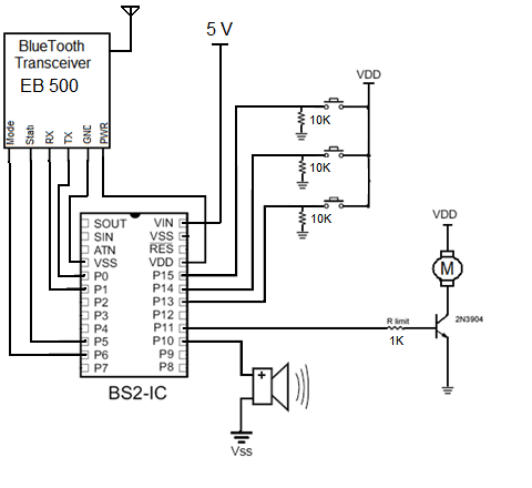
Minimum Circuit for BS2?
Hello,
I am working on a school project.· I've built and debugged my circiuts and code using a Board of Education.· I'm now in the process of building my own PCB to fit in·a specific·enclosure.· I am planning to program the stamp with the BOE and transfer it to a header on the custom board.··Please take a look at the attached schematic.· Will it work in this manner or is something else nescessary?
Thanks,
Dusty


Comments
▔▔▔▔▔▔▔▔▔▔▔▔▔▔▔▔▔▔▔▔▔▔▔▔
Think Inside the box first and if that doesn't work..
Re-arrange what's inside the box then...
Think outside the BOX!
frying it.
Where's the 5v coming from? a regulated source or just a battery? Its best not to tax the BS2's regulator too much.
Like Metron9, I don't know much about the bluetooth module, but you need to find out what its peak current consumption is and compare it to what the stamp's regulator can put out.
I run an eb501 off VDD quiet successfully. However, I provide VIN with 12 volts. It appears Handtool is powering VIN with 5 volts and taking 5 volts off VDD. I did not know that was possible. However, I am certainly not an expert.
--Bill
▔▔▔▔▔▔▔▔▔▔▔▔▔▔▔▔▔▔▔▔▔▔▔▔
You are what you write.
And depending on your speaker/transducer type, you may have to change your circuit. A regular speaker will need a series·electrolytic cap (per typical manual info); a·driven piezo element may need a parallel resistor to drain the residual charge. But if it's a piezo beeper that takes a steady +5 volts, you're all set.
▔▔▔▔▔▔▔▔▔▔▔▔▔▔▔▔▔▔▔▔▔▔▔▔
·"If you build it, they will come."
Handtool: The onboard regulator on the BS2 will reduce your 5volt to lower than 5v coming out of VDD.
If your 5volt input is regulated and completely clean, you can feed that right into
VDD with nothing connected to VIN and it should run fine.
▔▔▔▔▔▔▔▔▔▔▔▔▔▔▔▔▔▔▔▔▔▔▔▔
When the going gets weird, the weird turn pro. -- HST
1uffakind.com/robots/povBitMapBuilder.php
1uffakind.com/robots/resistorLadder.php
--Bill
▔▔▔▔▔▔▔▔▔▔▔▔▔▔▔▔▔▔▔▔▔▔▔▔
You are what you write.