

Schematic and Board Help
 RICoder
Posts: 91
RICoder
Posts: 91
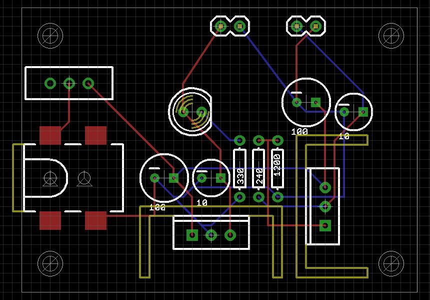
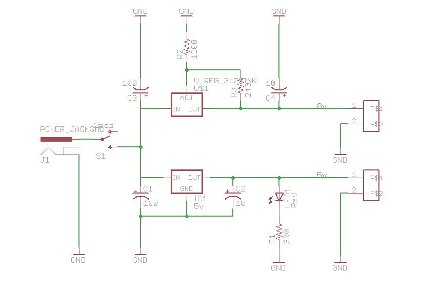
I have played around with a few of the apps out there for designing schematics and boards, and now that I have selected one, I'd like some feedback on my first board design. It is supposed to be a +5 / +8 regulated power supply. Images attached for both the board and schematic.
Please feel free to brutalize me on any topic, including naming conventions or style or personal flare or really anything either subjective or objective. Thanks.
FYI: I chose Eagle over PCBExpress because, while PCB was easier to learn, I found it lacking on power and functionality. God bless SparkFun for their awesome tutorials.
860 x 599 - 106K
860 x 561 - 29K
Comments
I am curious based on the complexity level of the power supply what features/power were lacking in ExpressPCB that you would require? I ask because as a user of both programs for some years now I still prefer ExpressPCB for all but the most complex designs. I tend to prototype almost everything in ExpressPCB and most people I know prefer the schematics generated by ExpressPCB over those from Eagle. I am just interested in hearing you input for future consideration when I release open-source projects. Take care.
▔▔▔▔▔▔▔▔▔▔▔▔▔▔▔▔▔▔▔▔▔▔▔▔
Chris Savage
Parallax Engineering
If I'm honest, the big pull for me from Express to Eagle was the auto-import from schematic and auto-routing. In addition, I am an old computer-geek of the worst kind, so where I might get away with using Sketch Up I'd rather use Turbo CAD because I KNOW it has more features, and more is better...right? While I find Eagle to be more complex, the detailed level at which you must design things makes me feel more in control of it, and the ability to link schematic parts to PCB parts I find to be intuitive.
When you create a schematic in ExpressSCH you assign component designators (and values) for each component. These would be unique, such as U1, U2, R1, R2, C3, etc. When you create a PCB in ExpressPCB you can link to the schematic. As you lay down parts you assign the corresponding designator used on the schematic. The link is to the net list from the schematic so what happens is when you click on a connection pad to route a trace all the connections on that net are highlighted, making it easy to see where the trace needs to go.
As for auto-routing, myself I never use it. I prefer to manually route my traces as the auto-router tends to make decisions that conflict with my design or at least neatness and the time spent tweaking the auto-router parameters and rules could be used to manually lay everything out. Oh, and since I forgot to mention it in the last message, congrats on your first board design. I still have pictures of some of mine…hand-drawn using a sharpie. Yeah, we won’t get into that here.
▔▔▔▔▔▔▔▔▔▔▔▔▔▔▔▔▔▔▔▔▔▔▔▔
Chris Savage
Parallax Engineering
I agree with Chris - I never use Auto-Router. You'll be much happier with the results if you route the board yourself.
And maybe use fixed value Regulators, you'll reduce your component count. And on the subject of regulators, if you feed the input of the lower voltage regulator from the output of the higher voltage regulator. The lower Voltage regulator doesn't have to drop as much voltage....thus lower heat build up. The drawback is, you limit the total current.
▔▔▔▔▔▔▔▔▔▔▔▔▔▔▔▔▔▔▔▔▔▔▔▔
Brian
uController.com - home of SpinStudio - the modular Development system for the Propeller
PropNIC - Add ethernet ability to your Propeller! PropJoy - Plug in a joystick and play some games!
SD card Adapter - mass storage for the masses Audio/Video adapter add composite video and sound to your Proto Board
▔▔▔▔▔▔▔▔▔▔▔▔▔▔▔▔▔▔▔▔▔▔▔▔
· -- Carl, nn5i@arrl.net
Leon
▔▔▔▔▔▔▔▔▔▔▔▔▔▔▔▔▔▔▔▔▔▔▔▔
Amateur radio callsign: G1HSM
Suzuki SV1000S motorcycle