SPI SRAM from microchip - More Prop Interface Questions
To Mike Green, or any,
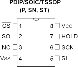
In another thread I proposed a method of increasing the through-put of the 23K256 serial SRAM from MicroChip by ganging multiple SRAMs in parrallel. (I have attached a schematic image of the device for reference.) Each would share the same clock pin, but the data in/out pins would be separated·and wired to different pins on the Prop.
I thought about this for a while and concluded, initially, that the input and output pins (SO and SI) would need to be connected to different Prop pins. Until I looked at the spec sheet more closely.
When I looked more closely,·I saw that SO is high-impedence when the device is reading data from SI. That lead me to conclude the input and output pins could be wired together and connected to the same pin on the Prop, as long as·the pin on the Prop is also high-impedence (set as an input) when the Prop is reading from SO.· This would clearly save a pin on the Prop.
I haven't looked at the current SPI objects in OBEX but, if I were a betting man, I would bet that those objects implement I/O on separate pins.·
This is too simple. Someone else must have clearly considered this and discovered some folly in it that I cannot see.
Can this be done?
Mark


Comments
Thanks for confirming that.
Mark
Usually in such applications you wire SI directly to the uC and insert a resistor between the SI and SO to limit the current in case of driving errors (SO and uC both outputs with opposite levels). This should work everywhere even if SO is not three-stated.
What resister value do you suggest?
Thanks.
Why is this a concern? The SPI out pin is tri-state when data is not active.
... if all else fails, read the instructions [noparse]:)[/noparse]
▔▔▔▔▔▔▔▔▔▔▔▔▔▔▔▔▔▔▔▔▔▔▔▔
--Steve
Thanks Mike
When dealing for example with SIPO/PISO registers that haven't the tristated output on two wire comunication usually you clock the bit in (uC output) then you change to input to read the output·(eg. of the last in chain that is connected throuh a resistor to the uC)·in the same clock period.
So, not all devices have tristate outputs: this is the solution to it this
Post Edited (dMajo) : 1/22/2009 5:43:51 PM GMT
... if all else fails, read the crystal ball [noparse]:)[/noparse]
▔▔▔▔▔▔▔▔▔▔▔▔▔▔▔▔▔▔▔▔▔▔▔▔
--Steve
▔▔▔▔▔▔▔▔▔▔▔▔▔▔▔▔▔▔▔▔▔▔▔▔
Timothy D. Swieter, E.I.
www.brilldea.com - Prop Blade, LED Painter, RGB LEDs, uOLED-IOC, eProto for SunSPOT, BitScope
www.tdswieter.com