

Building my own power supply. Need a sanity check.
 RICoder
Posts: 91
RICoder
Posts: 91
I have already built out a regulated 5v power supply that can use a wall-wart and push out some good 5v. That said, I recently got the propeller (having only used s BS2 on a BoE before), and found that it takes VIN from the 9V battery and puts out 5v.
So, I was going to get a couple of boards printed and make a few home-made power supplies for my projects. Now that I look at the prop, I am thinking that I'd like to make my boards so that they can take in a wart and put out either or both 5v and 8v.
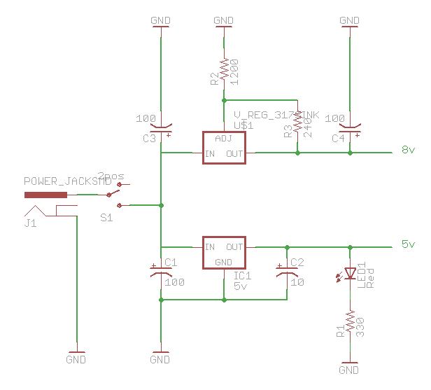
I drew up a schematic (attached) using a 5v regulator and a variable regulator...can you guys take a look and tell me if it is going to explode or not?
Thanks.
edit: FYI I think that C4 should be 50uF instead of 100uF...or maybe 10uF...
So, I was going to get a couple of boards printed and make a few home-made power supplies for my projects. Now that I look at the prop, I am thinking that I'd like to make my boards so that they can take in a wart and put out either or both 5v and 8v.
I drew up a schematic (attached) using a 5v regulator and a variable regulator...can you guys take a look and tell me if it is going to explode or not?
Thanks.
edit: FYI I think that C4 should be 50uF instead of 100uF...or maybe 10uF...
616 x 557 - 23K
Comments
a) Can I build a board that takes power from a DC wall wart and have multiple outputs at multiple voltages?
b) In my above schematic, assuming that the resistors for the variable regulator are correct, will I get what I want which is 5v and 8v (or 3.3v if I so wish it, maybe I'll make a 3 pointer)?
a) Yes
b) Yes, if you wanted to get tricky, you could take the difference of 8V and 5V and provide 3V (<-enough to power the Propeller) with the 5V/8V schematic you currently have.
▔▔▔▔▔▔▔▔▔▔▔▔▔▔▔▔▔▔▔▔▔▔▔▔
Beau Schwabe
IC Layout Engineer
Parallax, Inc.
Oh RICoder if I am not mistaken the propsticks are the ones that take in 9V battery power and then have the 3.3 output I do not hink the stand alone prop chip has the regulated out put on pin 32 I made that mistake I have the propstick so when I built a project with a plain 40 pin prop chip I powered it up with 9-10 volts and it got red hot before I realized my blunder
Post Edited (mikediv) : 1/22/2009 7:51:45 PM GMT
·Thank you for your post. It appears that I overlooked one item that I was searching for, and found it within your post. This will help immensely with my own project-enough so that I can put the draft together and submit for redline and review. (BTW, I'll have to make modifications to the schematic, adding extra filtering etc, due to the fact that (If approved) it'll be attached to flight hardware. I do hope that you do not mind me borrowing your schematic and doing modifications to it?
Dave