MSE-S110.2 sensoor!
Hi all!
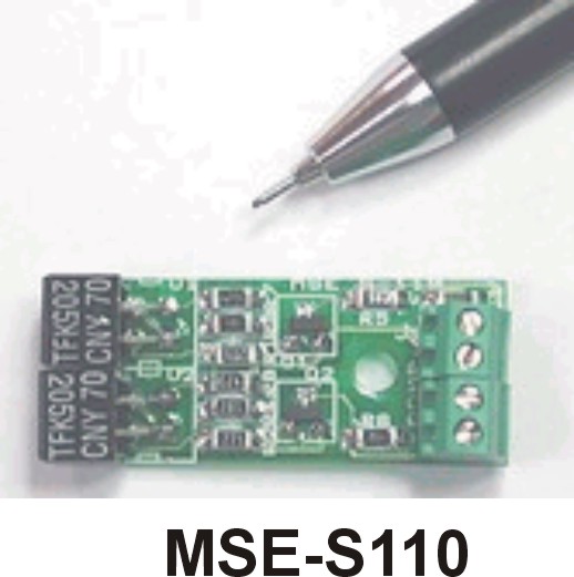
Weell I have onee problem... I bought the MSE-S110.2 sensor, but I don't know how to connect it to my Home Work Board.
Can someonel tell me how to connect it?
I attach a photo of the sensor.
▔▔▔▔▔▔▔▔▔▔▔▔▔▔▔▔▔▔▔▔▔▔▔▔
Sorry for my english, I'm spanish.
Post Edited (Izzy) : 1/19/2009 7:06:01 PM GMT
Weell I have onee problem... I bought the MSE-S110.2 sensor, but I don't know how to connect it to my Home Work Board.
Can someonel tell me how to connect it?
I attach a photo of the sensor.
▔▔▔▔▔▔▔▔▔▔▔▔▔▔▔▔▔▔▔▔▔▔▔▔
Sorry for my english, I'm spanish.
Post Edited (Izzy) : 1/19/2009 7:06:01 PM GMT


Comments
I can upload all the info that I have
▔▔▔▔▔▔▔▔▔▔▔▔▔▔▔▔▔▔▔▔▔▔▔▔
Sorry for my english, I'm spanish.
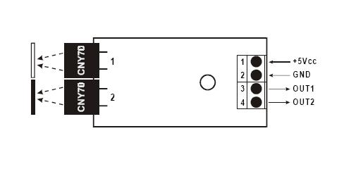
This is a Black/White detector with a dual head,· When you apply +5V and GND to the sensor, each sensor head has a separate output.
When the sensor detects A·dark line, object, etc., the output for that sensor goes HIGH(+5V).· Likewise when the sensor detects a light line, object, etc., the output for that sensor goes LOW(0V).
I would treat the output form the sensors the same way as a switch.
See: What's a Microcontroller·starting on page 71 and working your way through some of the exercises
▔▔▔▔▔▔▔▔▔▔▔▔▔▔▔▔▔▔▔▔▔▔▔▔
Beau Schwabe
IC Layout Engineer
Parallax, Inc.
So I must connect the sensor like the switch? I mean with the circuit as the photo?
Izzy.
▔▔▔▔▔▔▔▔▔▔▔▔▔▔▔▔▔▔▔▔▔▔▔▔
Sorry for my english, I'm spanish.
·
SRLM is correct... if you consider the Switch and Pull-down resistor to be as one device or unit providing an output HIGH or LOW depending on the state of the switch ...·Then you can also look at your device as thought it were a switch providing a·HIGH or LOW output depending on what it is looking at.
·
Saying that, the output(s) from your sensor should go through a 220 Ohm resistor as SRLM suggested before they go to any of the I/O pins.· This is just to protect the I/O pins of the Stamp from any accidental damage that could be caused with a short.
·
The example code that is given for the switches should work for your sensor enough to help get you going.
·
▔▔▔▔▔▔▔▔▔▔▔▔▔▔▔▔▔▔▔▔▔▔▔▔
Beau Schwabe
IC Layout Engineer
Parallax, Inc.
OUT 1/2 of Device
/\/\/\/ 220 Ohm \/\/\/\/\
I/O pin of your choice
Then, you can use the same code that a button would use.
Thanks SRLM and Beau~
If I have more questions I will post them =P
Izzy
P.S: I forgot to say that this sensor is for a Line Follower HOMO-BOT (HomeWork Boe-Bot)
▔▔▔▔▔▔▔▔▔▔▔▔▔▔▔▔▔▔▔▔▔▔▔▔
Sorry for my english, I'm spanish.
Post Edited (Izzy) : 1/19/2009 10:29:56 PM GMT
Jax
▔▔▔▔▔▔▔▔▔▔▔▔▔▔▔▔▔▔▔▔▔▔▔▔
If a robot has a screw then it must be romoved and hacked into..
but I didn't get that the sensors run, can someone upload a photo or something where I can see it how to connect them well?
Thanks in advance,
Izzy.
▔▔▔▔▔▔▔▔▔▔▔▔▔▔▔▔▔▔▔▔▔▔▔▔
Sorry for my english, I'm spanish.