

H-bridge circuit?
 Curtis Brooks
Posts: 38
Curtis Brooks
Posts: 38
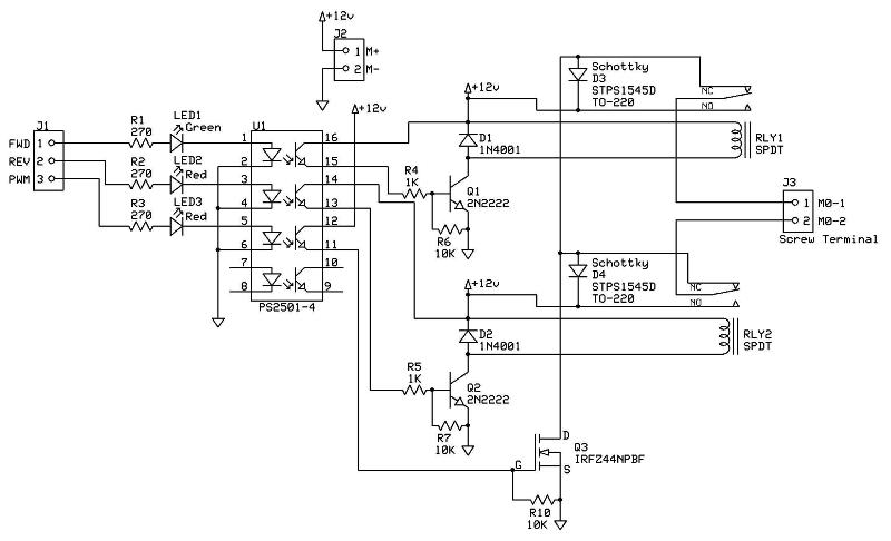
Will someone be so kind as to take a look at this H-bridge circuit for accuracy? I'm looking to develop a cheap high-current circuit and still use PWM. Specifically, did I get the flyback diodes right?
I placed the high-speed Schotkky clamping diodes in the circuit to protect the MOSFET from the CEMF generated by the motor as the power is switched on/off via the PWM signal. This will help keep the FET from generating to much heat and destroying itself. Also, the Optoisolator is a fast-switching type that will help ensure the MOSFET is switched on/off quickly. The opto has a fast rise/fall time. The relays are set up in an H-bridge configuration while the FET is used for the PWM signal. If anyone finds errors in this design please post them.
Thanks,
Curtis
** Updated 04 Jan 09 **
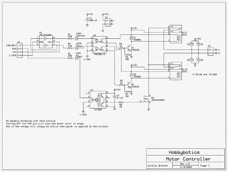
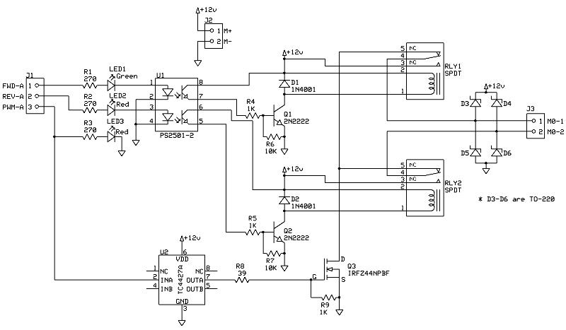
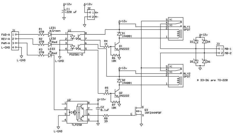
I updated the schematic to add some extra protection and a MOSFET driver. Please review and provide input.
I left the old schematic uploaded as well for comparison
** Updated 10 Jan 09 **
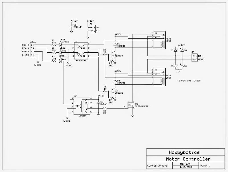
I updated the schematic yet again. I updated the original schematic to show isolation of the logic grounds from the motor grounds.
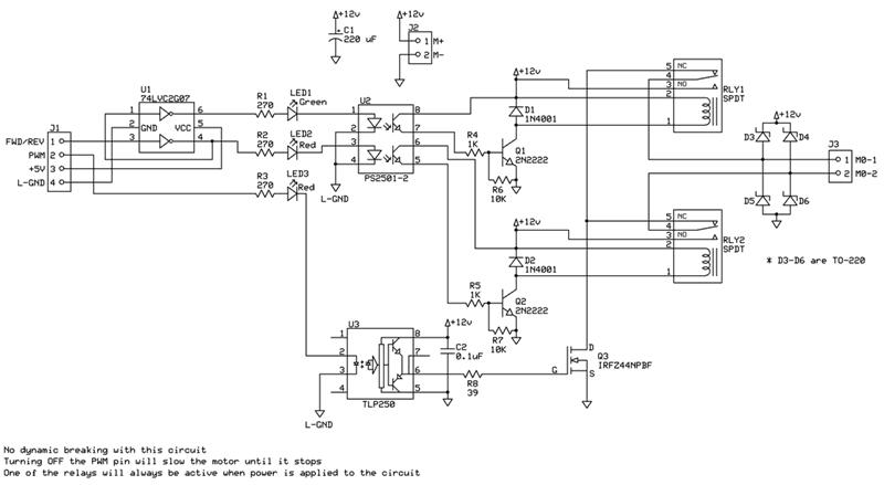
Updated the schematic for those that want to save an I/O pin. There is a Hex Inverter/Buffer circuit (U1) that feeds the inputs of the Optoisolator (U2). If you look at the wiring for the Hex Inverter you will notice that the output of the second inverter feeds the input of the first inverter. So, when a logic 1 is placed across pin-3 it is inverted into a logic 0 which turns off the Reverse Relay. A logic 0 is also placed at the input of the first inverter which gets converted to a logic 1 on its output and turns on the Forward Relay.
By using the inverter circuit you will no longer have the capability for dynamic breaking. In other words, one of the relays will be active as longs as powered is applied to the circuit. Disabling the PWM signal will keep the motor from turning.
I left the old schematic uploaded for comparison
Thanks,
Curtis
Post Edited (Curtis Brooks) : 1/10/2009 9:49:02 PM GMT
I placed the high-speed Schotkky clamping diodes in the circuit to protect the MOSFET from the CEMF generated by the motor as the power is switched on/off via the PWM signal. This will help keep the FET from generating to much heat and destroying itself. Also, the Optoisolator is a fast-switching type that will help ensure the MOSFET is switched on/off quickly. The opto has a fast rise/fall time. The relays are set up in an H-bridge configuration while the FET is used for the PWM signal. If anyone finds errors in this design please post them.
Thanks,
Curtis
** Updated 04 Jan 09 **
I updated the schematic to add some extra protection and a MOSFET driver. Please review and provide input.
I left the old schematic uploaded as well for comparison
** Updated 10 Jan 09 **
I updated the schematic yet again. I updated the original schematic to show isolation of the logic grounds from the motor grounds.
Updated the schematic for those that want to save an I/O pin. There is a Hex Inverter/Buffer circuit (U1) that feeds the inputs of the Optoisolator (U2). If you look at the wiring for the Hex Inverter you will notice that the output of the second inverter feeds the input of the first inverter. So, when a logic 1 is placed across pin-3 it is inverted into a logic 0 which turns off the Reverse Relay. A logic 0 is also placed at the input of the first inverter which gets converted to a logic 1 on its output and turns on the Forward Relay.
By using the inverter circuit you will no longer have the capability for dynamic breaking. In other words, one of the relays will be active as longs as powered is applied to the circuit. Disabling the PWM signal will keep the motor from turning.
I left the old schematic uploaded for comparison
Thanks,
Curtis
Post Edited (Curtis Brooks) : 1/10/2009 9:49:02 PM GMT
800 x 486 - 41K
800 x 467 - 41K
800 x 439 - 38K
800 x 463 - 39K
Comments
He's using the PWM to throttle the Ground through the Q3... the Relays are for direction control.
▔▔▔▔▔▔▔▔▔▔▔▔▔▔▔▔▔▔▔▔▔▔▔▔
Beau Schwabe
IC Layout Engineer
Parallax, Inc.
I have used something very similar with RC cars that don't need to go in reverse much.... only I use a single DPDT relay for direction with it being energized for reverse.
The only thing that I can see, and this depends on the intended design, is that you have a HARD electrical brake to the motor when the FWD and REV relays are in the same position. This can cause abrupt stops if your intention is to free-wheel. But as I said it depends on the design, in some cases this feature might be desirable.
▔▔▔▔▔▔▔▔▔▔▔▔▔▔▔▔▔▔▔▔▔▔▔▔
Beau Schwabe
IC Layout Engineer
Parallax, Inc.
Thanks to all for the help,
Curtis
Should be ok, those FET's are rated for about 50 Amps with an Rds "ON" of 17.5 milli-Ohms.
▔▔▔▔▔▔▔▔▔▔▔▔▔▔▔▔▔▔▔▔▔▔▔▔
Beau Schwabe
IC Layout Engineer
Parallax, Inc.
▔▔▔▔▔▔▔▔▔▔▔▔▔▔▔▔▔▔▔▔▔▔▔▔
Tracy Allen
www.emesystems.com
I was thinking of using a Microchip TC4427 1.5A Dual High-Speed Power MOSFET Driver or TLP250 Photocoupler Power MOSFET Gate Driver instead of driving the MOSFET with the PS2501 optocoupler as it was suggested that it will provide more current to the gate of the FET. Any thoughts on whether this will be better than the current design?
Thanks to all for the help/suggestions
▔▔▔▔▔▔▔▔▔▔▔▔▔▔▔▔▔▔▔▔▔▔▔▔
Tracy Allen
www.emesystems.com
Also, I hope someone else finds this all useful. I plan to add a Melexis 90217 Hall-Effect Sensor for RPM feedback.
The TC4427 is an active driver and does need a pulldown on its input in case the PWM input is disconnected or fails open, and in that earlier circuit, the LED with its resistor serve as the pulldown. The TLP250 in the current schematic is a very different beast. It is a glorified optocoupler with internal level shifting and a totem pole output connection. Its spec sheet states that its output will be low when its input LED is off, so the mosfet would be off, as it shoud be, when the PWM input is floating.
To save parts, I'd be tempted to go back to the original circuit with only the quad PS2501 optocoupler, and use the 4th section as an active pulldown for a totem pole arrangement. When the PWM input is active low, it turns on the 4th LED, which turns on the 4th transistor, which is connected in series with a 270 ohm resistor from gate to source on the power mosfet. Keep the ~10k resistor in parallel direct from gate to source to keep the mosfet off when there is no input.
▔▔▔▔▔▔▔▔▔▔▔▔▔▔▔▔▔▔▔▔▔▔▔▔
Tracy Allen
www.emesystems.com
Thanks,
Curtis
I see what you are refering to.· Actually the logic grounds from the opto and driver will not be grounded to the same as the motor.· I suppose I should've made that clearer in the schematic.· I will fix it and repost.
Thanks,
Curtis
Post Edited (Curtis Brooks) : 1/6/2009 11:34:38 PM GMT