

Shift Register Help Please
 babinda01
Posts: 54
babinda01
Posts: 54
Hi Everyone,
I have a very newbie question here, so please excuse my ignorance.
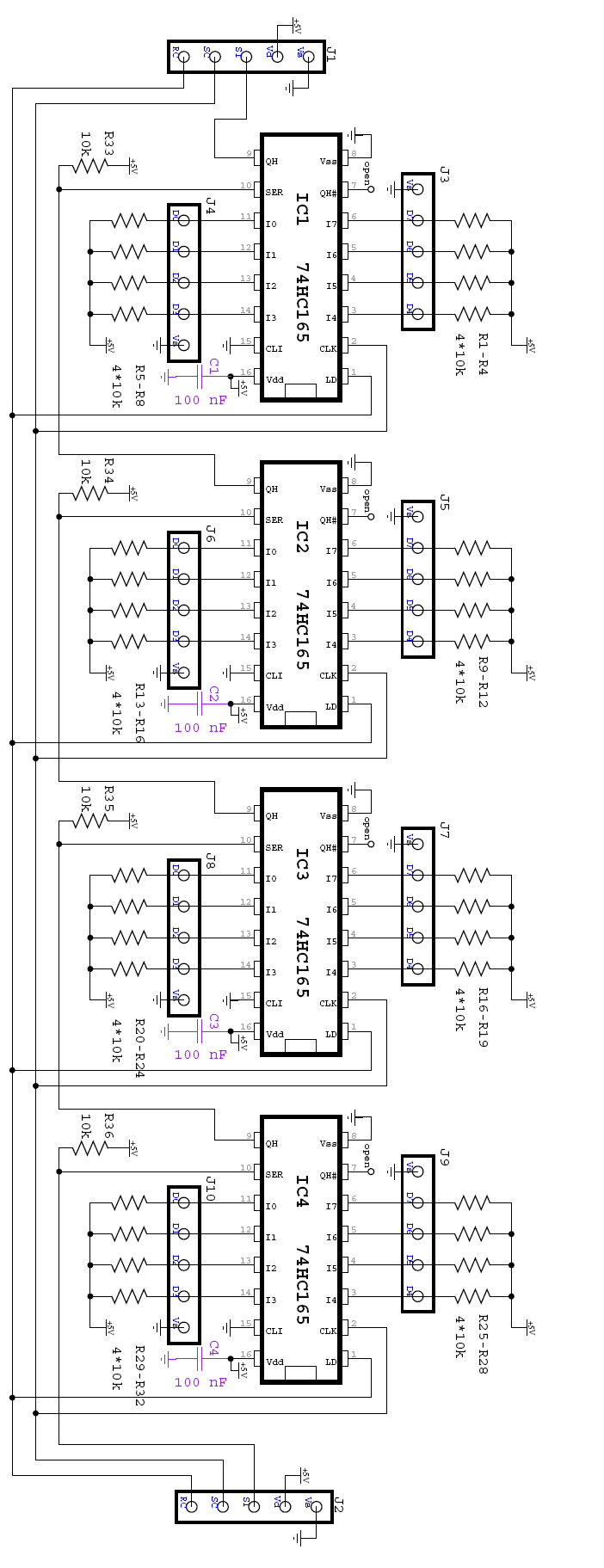
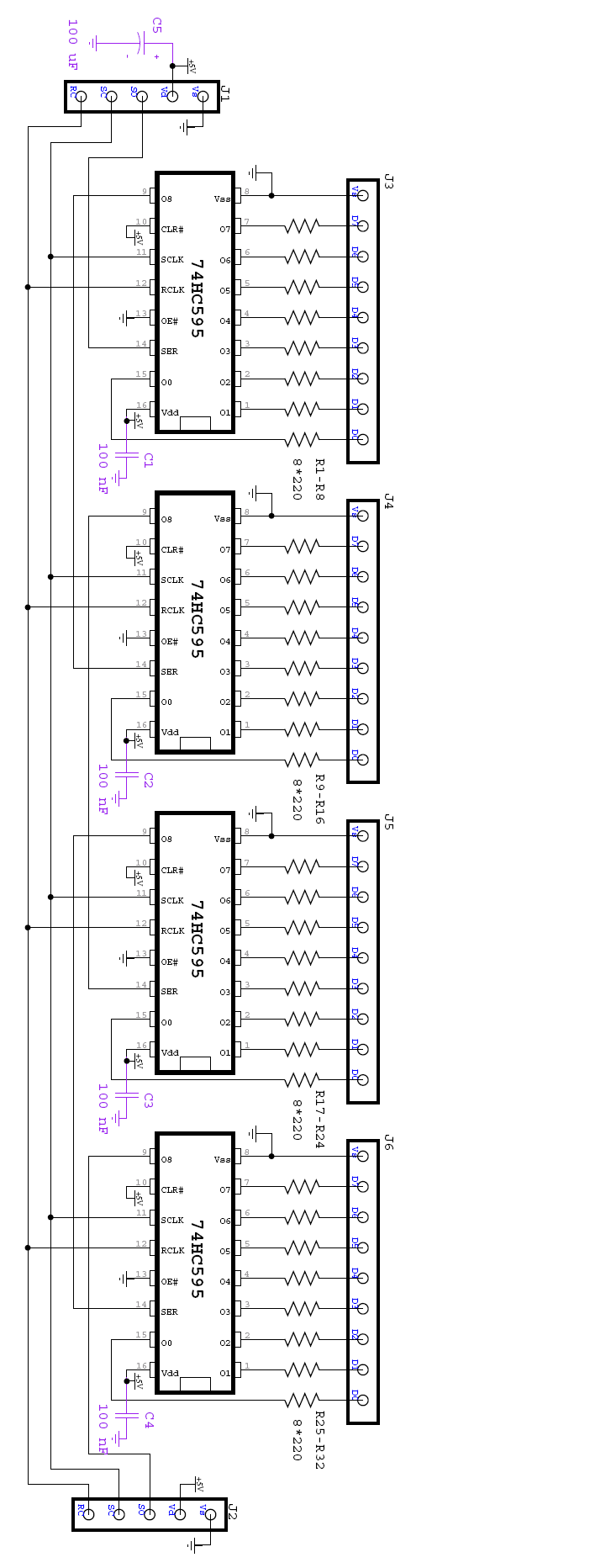
I am trying to interface 40 momentry push buttons and 4 x 6 position rotary switches to the prop chip using 74HC165 shift registers, and then led indicators for all of the switch contacts via 74HC595 chips.· I found the attached schematics on the internet and have made a board for the switches and another board for the leds.
My question is, how do I hook the signals SO, SC, RC for the 595 and SI, SC, RC for the 165 to the prop? I am supplying the 5V and 0V for my prop board (I have a seperate 7805 reg for the 5V). I have read that I should put a 1K resistor in series with the signals, but do I do this for all three of the signals from each chip.· Do I use 6 pins of the prop for this(three for each chip), or is there some way I can daisy chain the 595's and the 165's together?· If anyone has a schematic they are willing to share it would help greatly.
Thanks for your help
Andrew
I have a very newbie question here, so please excuse my ignorance.
I am trying to interface 40 momentry push buttons and 4 x 6 position rotary switches to the prop chip using 74HC165 shift registers, and then led indicators for all of the switch contacts via 74HC595 chips.· I found the attached schematics on the internet and have made a board for the switches and another board for the leds.
My question is, how do I hook the signals SO, SC, RC for the 595 and SI, SC, RC for the 165 to the prop? I am supplying the 5V and 0V for my prop board (I have a seperate 7805 reg for the 5V). I have read that I should put a 1K resistor in series with the signals, but do I do this for all three of the signals from each chip.· Do I use 6 pins of the prop for this(three for each chip), or is there some way I can daisy chain the 595's and the 165's together?· If anyone has a schematic they are willing to share it would help greatly.
Thanks for your help
Andrew
702 x 1823 - 114K
702 x 1864 - 104K
Comments
both chips work within 2V-6V so why not supplying them with 3.3V ?
I did this with 74HC595 and 74HC597 and it worked great
It might be possible to do switch one prop-IO-pin between input and output but therefore I think a pull-up-resistor is required
To make sure that the IO-state of the shared serialdata-pin do NOT interfere with each other you have to take a very close look
onto the logic table of both chips. You have to avoid that both chips get a "load parallel" signal. the 165 loads in whenever PL is low
RCK of 595 is triggered on a low-high-transistion
I guess you need an inverter to transform the low-high-transition of the 165 into a high-low-transition of the 595. AND it must be possible
to have the "load-parallel"/store parallel pin then "the other" state and everything else (data in/output shift-clocking) is still working
As I made a QUICK look at the truth-table it should be possible to share the pins when between Prop-IO "palallel-load" and 595 is an inverter.
But I would test this INTENSIVLY before manufacturing a PCB.
best regards
Stefan
*Peter*
74HC165
PROP
QH
10K
>DAT
CLK <
CLK
LD <
LD (active low will read inputs then)
74HC595
PROP
SER <
DAT
SCLK <
CLK
RCLK <
LD (low to high) (double up with 74HC165)
As for the signals:
SC (shift clock) both chips shift the data on the low to high transition of the clock so it can be shared. Use a low to high pulse.
RC (register load clock) the 165 loads the register when it is low, and 595 loads the output register on the low to high transition so it can be shared if you use a low to high pulse.
If the data bits going out to the leds are in the same order as those coming in from the 165 then you will not need an output pin. You can connect the output from the 165 to the input of the 595 and the prop input pin. Otherwise you will need an output pin from the prop connected to the input of the 595.
Be aware that:
J2 is the serial input to the 165 chain and J1 is the serial output.
J1 is the serial input to the 595 chain and J2 is the serial output.
This is only relevant if you want to connect the serial out from the 165 to the input of the 595. SC and RC are common to both connectors.
RC (register load clock) the 165 loads the register when it is low, and 595 loads the output register on the low to high transition so it can be shared if you use a **** high to low***** pulse.
Thanks for all the replys.
I have plenty of I/O left on the prop so I have no problems using 3 pins for inputs and another three for outputs, if that is ok to do.
I will run them driectly from the 3.3V from the prop (nice and simple).
I will make a board up now, and wil give it a try.· Thanks again for everyones help.
regards
Andrew
·
Good luck,
Kurt
I'm normally squeezing every last breath out of the I/O pins and things like LEDs and switches don't need dedicated lines. If it was just the leds then I would connect the clock and data to the I2C lines and just use one other I/O for the load.
As for the code being simpler or more complex I find that there is hardly any difference anyway, just simple clock and data as normal.
*Peter*