

Provide feedback on adc board for prop
 Will__S
Posts: 19
Will__S
Posts: 19
Hi all,
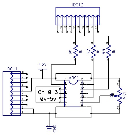
I'm in the process of creating my first pcb, and was hoping to get some feedback. The board is an analog/digital converter for some sharp ir sensors I'm using (3 pin interface [noparse][[/noparse]gnd, +5v, sig]). I know the prop can do this natively, but I had some issues with wild readings (probably due to the distance from the prop, and a sloppy proto board). I decided to use the adc0834bcn chip (data sheet http://www.parallax.com/Portals/0/Downloads/docs/prod/datast/dsadc0831.pdf ). The pcb I'm creating is an add-on to the spin studio main board, and will be connected via a 20pin idc ribbon cable to port D.
While scouring old posts for pcb tips, I came across a discussion that mentioned putting a .1uF cap on the power input of ics, and especially the prop. Is this necessary for all ics?
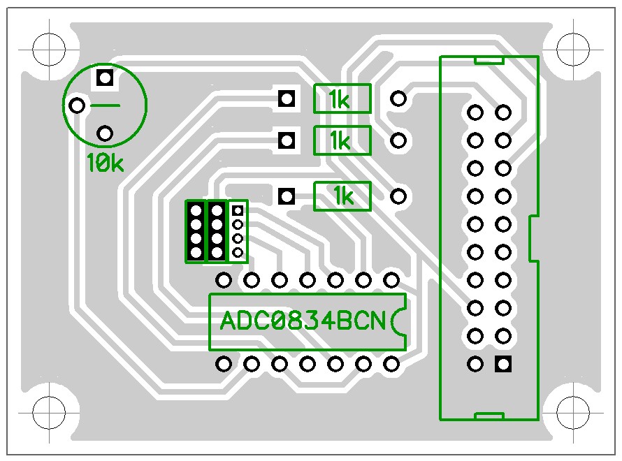
My hope is to make one board at home for fun, and if all goes well, have a shop make a few. As such, the design is single layer. Attached is my schematic, and layout.
All input on the schematic and layout is greatly appreciated.
Thanks,
Will
I'm in the process of creating my first pcb, and was hoping to get some feedback. The board is an analog/digital converter for some sharp ir sensors I'm using (3 pin interface [noparse][[/noparse]gnd, +5v, sig]). I know the prop can do this natively, but I had some issues with wild readings (probably due to the distance from the prop, and a sloppy proto board). I decided to use the adc0834bcn chip (data sheet http://www.parallax.com/Portals/0/Downloads/docs/prod/datast/dsadc0831.pdf ). The pcb I'm creating is an add-on to the spin studio main board, and will be connected via a 20pin idc ribbon cable to port D.
While scouring old posts for pcb tips, I came across a discussion that mentioned putting a .1uF cap on the power input of ics, and especially the prop. Is this necessary for all ics?
My hope is to make one board at home for fun, and if all goes well, have a shop make a few. As such, the design is single layer. Attached is my schematic, and layout.
All input on the schematic and layout is greatly appreciated.
Thanks,
Will
446 x 465 - 40K
890 x 660 - 126K
Comments
Most logic ICs these days switch in the ns range and electricity can travel only a few inches in that timeframe. In particular, it can't flow from your power supply to the IC in that amount of time so you need a local reservoir, hence the 0.1uF capacitor.
This is more of a question than help for Will, although his ADC board design brought it to my mind ...
On an analog pcb are there any negative consequences to having areas of the board 'filled in' but not connected to ground, for example? I guess I am thinking of stray capacitance issues and so forth.
Cheers!
I'd use wire links instead of those long tracks.
Leon
▔▔▔▔▔▔▔▔▔▔▔▔▔▔▔▔▔▔▔▔▔▔▔▔
Amateur radio callsign: G1HSM
Suzuki SV1000S motorcycle
Post Edited (Leon) : 1/2/2009 4:14:38 PM GMT
You might consider using an MCP3208 instead of the chip you're using.
It's very easy to interface to the Prop, has drivers available and will give you eight 12 bit adc's instead of the 8 bit you have.
I've used it with IR sensors with good results.
If you want schematics or code samples, let me know.
Jim
(Sorry to one up you Jim!)
When you etch it and the drill them there will not me much to solder to. It will also have a tendency to pull up with heat from the soldering iron. The square pads on the resistors are much better.
.02c
chad
You're right about the TLV chip. It converts faster and allow a much faster clock than the MCP3208.
I rewrote Chip's driver for the MCP3208, so I can now get more than 10,000 individual samples/sec.
I can also get more than 4,000 10-sample averages per second.
I'm still happy with the MCP3208 and I never need anything this fast anyway, yet[noparse]:)[/noparse]
Question for you about the TLV driver. You said it keeps running averages of the adc values.
Does it also provide individual samples if needed? When I run the data thru a Kalman filter,
I need individual samples to get the right answers. Averages don't work as well.
I wrote a program to track the altitude and velocity of a rocket by reading the air pressure.
In this case the Kalman filter needed individual samples to get the actual variance of the data.
Thanks for the info. I may switch to the TLV when I get some free time to look at it.
Jim
Jim and Phil,
Thanks for the chip suggestions, I wish I would have asked for suggestions before purchasing a few of the adc0834s.
I've reworked the pcb a little, but had a few questions.
Leon, you mentioned using jumper wires instead of the long traces. Were you referring to just the ground traces?
I've removed the solder pour, and used jumpers for the gnd connection.
I was reading that having a ground plane helps remove odd glitches especially for the prop. Should a ground plane be used when ever possible? Should I still keep the solder pour and just use jumper wires to connect the larger areas, and remove the small unconnected areas? Is the prop especially sensitive, or is this mainly a consideration for the board the prop is directly mounted to?
What is a good thickness for the pads and holes for a home brew board. Would making all of the pads square be ill-advised?
Attached is my newer revision of the board and schematic.
Thanks again for all the help,
Will
If you are working with a single sided PCB and you need to have jumpers then do this to signal lines but avoid doing this to the ground as you have on your pcb. Allow for capacitors on the ADC inputs even if you don't end up using them, having extra tracks and pads doesn't cost anything. Also pour out that ground as much as possible around the outside of the board and up between all those sensitive reference and input lines.
*Peter*
When I say "running average", I'm refering to the X = (X + (New X))/2 method. In Tim's driver, from what I understand from the assembly, it takes the previous sample, multiplies it by 7, adds the new sample to that, and divides the total by 8. This way the new sample contributes only 1/8th of the actual value. Looking at the code, it would be easy to store the ACTUAL value... in fact, doing so would increase the sample rate since each cycle won't have to compute this average. Like I said, you can go to the TI website and order some samples of the chip to try it out. It comes in DIP, SOIC, and AMAZING packages. Well, not the last one, but I just love this chip. I'd use it even if I only needed ONE channel.
Oh, one other thing as far as references go. If you DO get some samples from TI, also check out their LM4040A series precision voltage references. They come in 5V, 2.5V, and other references and the "A" means it's 0.1% accuracy. Using these with the TLV2543, and good wiring gives extreme accuracy. I don't get all tingly about chips very often, but this combo gives me the shivers. Yes, I'm a nerd.
*Grounded* copper pour is a good idea, especially for an ADC. You should remove all unconnected "islands", the software I use doesn't create them in the first place.
I meant that you should use jumpers for your signal tracks - they should be as short as possible.
Round pads are best, some people use a square pad to indicate pin 1 on a part.
12 mil tracks and 60 mil pads are what I'd use, if you've just started making your own boards.
Leon
▔▔▔▔▔▔▔▔▔▔▔▔▔▔▔▔▔▔▔▔▔▔▔▔
Amateur radio callsign: G1HSM
Suzuki SV1000S motorcycle
Thanks for the feedback on the TLV chip.
I really like your idea about using an accurate voltage reference.
I've always noticed that the reference voltage is a little 'off'.
Would you be willing to share your circuit for connecting the LM4040A to the TLV reference line?
I can probably figure it out, but why re-invent the wheel[noparse]:)[/noparse]
Jim