

Wish Id have spent more time in the EE department - BS2 PLC ADC and a pressure
 Wildatheart
Posts: 195
Wildatheart
Posts: 195
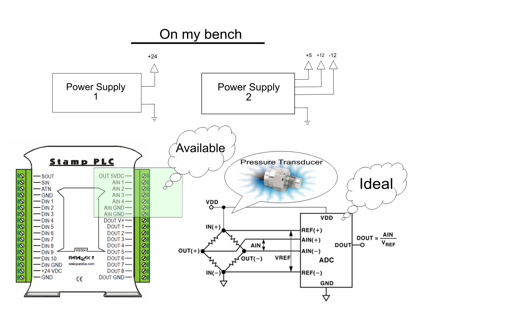
In the two attachments…· 1 shows the items on my bench, and 2 is a data sheet from a pressure transducer.· I would like to connect the transducer to my Stamp PLC but I don’t see a place on the PLC to connect the negative out of the transducer.· And also, the requested excitation of the transducer is 10vdc (15vdc max), so I’d like to use the aux power supply +/- 12 vdc as appropriate.· Also, while asking·for help to connect the transducer to the PLC, should all the grounds be tied together if I use the aux power supply?
Attachment 2 is at:
http://www.kulite.com/pdfs/pdf_Data_Sheets/HKM-375.pdf
Thanks in advance for taking time to help.
1680 x 1050 - 164K
Comments
It is ok for the IN(+) to go to the 12V supply, but the IN(-) should go to ground ... NOT the -12V supply.
In order for the ADC to properly communicate with the BS2, the ADC needs to also operate at 5V. This also means that the input voltage to the ADC should be within 5V as well.
Since the output impedance is 1k you can use a voltage divider consisting of a 150k and 100k resistor on the OUT(+) and OUT(-) with minimal effects. (<--less than 0.4%)
See attached image for an example connection. Note: ADC should be configured to operate in differential mode.
▔▔▔▔▔▔▔▔▔▔▔▔▔▔▔▔▔▔▔▔▔▔▔▔
Beau Schwabe
IC Layout Engineer
Parallax, Inc.
I do have a LTC1298 and will be ordering another BS2 soon, so I intend to use the detail you’ve provided for yet another similar sensor.·
In the case of the pressure transducer, perhaps I should have been clearer – the Stamp PLC accepts only accepts the MAX1270 A/D converter.· ··As you know, this device is software programmable to accept a wide range of inputs.·
The MAX1270/MAX1271 are multirange, 12-bit data acquisition
systems (DAS) that require only a single +5V
supply for operation, yet accept signals at their analog
inputs that may span above the power-supply rail and
below ground. These systems provide eight analog
input channels that are independently software programmable
for a variety of ranges: ±10V, ±5V, 0 to
+10V, 0 to +5V for the MAX1270; ±VREF, ±VREF/2, 0 to
VREF, 0 to VREF/2 for the MAX1271. This range switching
increases the effective dynamic range to 14 bits and
provides the flexibility to interface 4–20mA, ±12V, and
±15V powered sensors directly to a single +5V system.
In addition, these converters are fault protected to
±16.5V;
Knowing this, would your advice be different for direct connection of the sensor to the Stamp PLC?· The Stamp PLC provides a +5vdc out and 2 Ain ground connections in the vicinity of the analog connection terminals.· This would be handy for reading a pot as illustrated, but are these significant, and do these restrict the use of the MAX1270 in the Stamp PLC?· I haven't been able to find documentation that details these connection points.
Thanks again.·· -gordon
Post Edited (Wildatheart) : 1/2/2009 2:00:21 PM GMT
I'm not familiar with the MAX1270 A/D converter, however it looks like it will take a +/-10V supply and is input tolerant up to +/-16.5V which means that if you use a +/-12V supply you will have clipping toward the extremes (<-- High positive pressure as well as a high negative pressure) which typically won't be a problem in most cases.
I am unclear as to whether you can configure the MAX1270 A/D converter in a differential mode, so you will need to implement something in software between the two channels that you are going to look at.
▔▔▔▔▔▔▔▔▔▔▔▔▔▔▔▔▔▔▔▔▔▔▔▔
Beau Schwabe
IC Layout Engineer
Parallax, Inc.
In order to use the MAX1270 effectively you would really need to add an analog(!) amplifier for the bridge, to convert the differential out(+) - out(-) to the single ended voltage.
My current favorite way to approach bridge sensors is with the AD1100 converter from TI. 16 to 19 bits differential with PDA and I2C interface, SOT23-6 package.
▔▔▔▔▔▔▔▔▔▔▔▔▔▔▔▔▔▔▔▔▔▔▔▔
Tracy Allen
www.emesystems.com
·
After reading the suggestions it is clear to me that the LTC1298 with its own BS2 is the solution here.· I’ll abandon the idea of using the Stamp PLC A/D converter and post the success here shortly.
·
BTW… I intend to install a bladder that is connected to the pressure sensor via an umbilical cord to a “submersible” for the purpose of monitoring its depth under water. ·Depending on settings, the PLC (or a Stamp) will make adjustments to its buoyancy by injecting or releasing compressed air in/from the submersible’s tanks.
·
A sensor can be had for as little as a penny on Ebay, and $14 lawn sprinkler valves work great under water.· Hopefully, all working together, they’ll perform buoyancy adjustment to add control to the system.·
·
Thanks to each of you for your advice.·· -gordon
PS· Perhaps I'll use the Stamp PLC A/D converters with simple joystick pots for position control.
You have a bridge circuit between ground and + 12 volts, so the signal you are measuring is the difference in voltage between the two legs (approx 100mV max), and that is sitting on top of a 6V DC level.
You have an analog power supply providing +- 12V, and unused ADC inputs on the Stamp PLC.
Would it not be simpler to feed the input of one leg to the inverting input and the other leg to the non inverting input of an op amp whose gain is set (25x-50x) to a value matching the input range of the Stamp ADC and use it?
The AD7705 is a little harder to program than the LT1298,·since you need to set the gain and zero points for the built in amplifier. You will also need a crystal for the internal clock of the chip.
Post Edited (MSDTech) : 1/3/2009 7:07:51 PM GMT