

My Propeller Widget!
 Peter Jakacki
Posts: 10,193
Peter Jakacki
Posts: 10,193
I just thought I would share this with the group as it is always interesting to see what everyone else is doing. A little while ago I featured one of my Propeller products which I recently updated. I basically designed this for use as an isolated universal USB to serial converter. Of course it was too tempting at the time not to include video and keyboard ports but the device was still limited in that it was designed to be powered via the USB port or an external +5V supply.
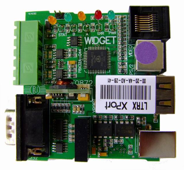
This newer design has the same footprint but also added the full complement of RS-232 signals for those oddball devices and besides on-board switch-mode regulation I also added an Ethernet port using the Lantronix XPORT module. Since there wasn't much room left for connectors I dropped the bulky DE-15 and replaced it with an 8-pin RJ-45. In doing so it means that I always need an adaptor cable to connect it to VGA but it also removes the bulky connector from the device and in doing so I was able to add composite TV and a mono audio output to the connector. In addition the PS/2 connector also has the I2C bus on the other two unused pins so that I can plug in special expansion devices if I am not using it for anything else.
I ran a demo recently where I was handling multiple serial ports and protocols and also running the "Spacies" game on a small 7" LCD TV. It used up all the cogs (wish I had more) but it ran so it is quite a powerful demonstration from what is really just a simple low-end device. The idea is that this device can be used for stand-alone terminals connected to the LAN or/and RS-485 buses etc. The sky's the limit.
WIDGET FEATURES::
RS-232 on DB9 with full signal complement of RXD,TXD,CTS,RTS,DTR,DSR,DCD,RI
RS-422 or dual RS-485 on 6-way Combicon terminals
ISOLATED USB based on FT232RL
XPORT LAN PORT
PS/2 Mouse/Keyboard/I2C on miniDIN6
Combo VGA or TV + mono audio on single RJ-45
Switch-mode supply for stand-alone operation up to 32V
*Peter*
640 x 593 - 72K
640 x 616 - 54K
739 x 480 - 37K
Comments
·
The RJ45 could also be used for RS232 as adapters are easy to get
▔▔▔▔▔▔▔▔▔▔▔▔▔▔▔▔▔▔▔▔▔▔▔▔
Prop Tools under Development or Completed (Index)
http://forums.parallax.com/showthread.php?p=753439
cruising][noparse][[/noparse]url=http://www.bluemagic.biz]cruising[noparse][[/noparse]/url][/url]
This is a [noparse][[/noparse]b]bold[noparse][[/noparse]/b] test.
Yes, I agree as I use RJ45s for RS-232 in many other designs but sometimes when you have a single port and room for it then it is nice to have something that you can plug directly into. At least the DB9 has a standard pinout but not so RJ-45 although I do favor the "YOST" symmetrical layout with both center pins grounded so that the cable can be mirrored to interconnect devices with the same pinout.
What I do detest with the RS-232 standard (not) is the different pinout of a device depending upon the archaic definition of DTE or DCE. Make them all the same I say and then there are no guessing games. If my device has a DB9 then I always make it a male with standard PC pinouts unless it's a custom device and the customer specifies something different. The second pet peeve is the unbending insistence of some that the archaic plus and minus voltages be handled by "a proper" RS-232 chip. So I include "proper" RS-232 for the transmitters but if I need extra receivers it is very easy to connect the signal via a resistor to a Prop I/O. Interestingly the switching threshold for a high or low for a "proper" RS-232 chip is never to RS-232 specification anyway but usually centers around +1.5V. So the input levels do not have to swing negative at all, usually anything less than +1V will do. Anyway, the Prop's input threshold centers around 1.5V, so what's the difference? Nobody can tell.
*Peter*
Originally the DCE was a DB25 female (modem) and the Terminal was a DTE using a DB25 male, and these were designed to connect with a straight through cable. If you wanted to connect two terminals (DTE male) you had to build a crossover cable. This was well understood in the 70's. Apple released a PCB using a DTE on a DB25 female and the mainframe community cringed. Then terminals started to use the female as well. This resulted in a confused and butchered specification. There was no confusion by the mini and mainframe computer engineers. Clocking was also provided on pins 15 & 17 (from memory) as most communications were synchronous back then. I designed and built all kinds of protocol converters including ASCII to EBCDIC. When we released an Apple Serial Card (Apple branded), it had the required DB25 male.
Originally the spec called for +-15V, although RS232E has reduced the voltage requirements. Most receiver circuits will work using >+3V for high and 0V for low, which translates to +1.5V with hystersis (don't forget inversion). For transmitters, often you can get away with +5V and 0V (which is a NMEAxxxx standard - marine instruments using just tx and rx and ground pins).
▔▔▔▔▔▔▔▔▔▔▔▔▔▔▔▔▔▔▔▔▔▔▔▔
Prop Tools under Development or Completed (Index)
http://forums.parallax.com/showthread.php?p=753439
cruising][noparse][[/noparse]url=http://www.bluemagic.biz]cruising[noparse][[/noparse]/url][/url]
This is a [noparse][[/noparse]b]bold[noparse][[/noparse]/b] test.
*Peter*
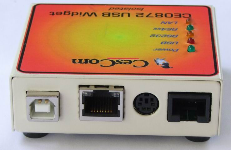
Very professional design, congratulations. There's no doubt about it, a neat metal case makes a world of difference (openstomp too)
Many moons ago I used some similar IP-to-Serial devices made by Sena. They had a Super series which had a 'third port' (apart from Serial and LAN) which was a PCMCIA slot. This allowed for all sorts of interesting applications such as data logging, parameter adjustment by CF card, even wifi. I'd love to see a SD card slot on your product but realise space is at a premium.
Recently I came across a modern improvement in the Netburner PK70. Its worth a look for ideas for a possible future model of yours. They leave room inside the case for the user to add their own board and external connector. To me this has a lot of appeal, since most of the hard work (industrial power, standard ports, case) is already complete.
A similar prop based design with its 8 cogs could really take advantage of such an arrangement.
But a truly great effort. I hope it sells well for you.
tubular
David
The metal case is more practical than an off-the-shelf plastic case would as the plastic case needs to be cut and that ends up costing more than a custom metal case. Of course custom injection mold is out of the question unless I am talking very large quantities to amortize the tooling costs.
As I hate using screws to secure pcbs I design the pcbs to slide in with two locating tabs finally resting in a slot on either side. The cover has two countersunk screws (unfortunately) to secure it to the sides of the base but once again it's a problem with tooling costs that prevents me from making this a complete slide and snap. I'm not quite sure what the cases cost as I try not to worry about stuff like this (I have a good association with a mate who handles the manufacturing) but I think that the cases end up costing around $15 (AUD) once we do a run of them. Here in Brisbane we use Samin and I believe that Metal Tech also do a good job as well.
Samples of the prototype labels are printed onto a polyester heavy duty label in a color laser printer so an A4 sheet ends up costing me around $2 total. Once we are happy with the labels we can get them produced normally knowing exactly what we will be getting back. For the label design I use OpenOffice Draw as it allows me to precisely line up all the features and gives me complete freedom to put whatever I want wherever I want (and it's totally free).
@Tubular: I have other Prop designs with standard SD cards and even microSD but a lot of my newer ones are allowing for those little 8-pin SMD DataFlash chips like the 8-megabit AT26DF081 as standard. I have an updated version of my iCONSOLE design that combines a Propeller and an ARM chip along with dual SD cards and various coms ports and LAN as well as a GPRS+GPS module. I think it's probably impractical to have a standard expansion slot because all the existing I/O is fully committed. Instead I rely on the expansion capabilities of various serial style buses, both internally and externally. In fact the SD slots can take SDIO cards such as those cool WLANs.
I also have a nice little MultiPLC product housed in a standard Phoenix DIN mount case that I can use standalone or as stackable slave I/O for a multitude of jobs as I can change the I/O modules to suit but I am still prototyping this one though.
www.cescom.com.au/products/CE-0810/CE0810DS.pdf
*Peter*