

Schematic to Circuit assistance
 flying_flip
Posts: 36
flying_flip
Posts: 36
I am laying up a circuit for the "Maximum LEDs" post.
Please review the attached pictures.
I need confirmation of my translation from Schematic to Circuit board.
I am going to have the boards professional done, so I want to make sure this 2 sections are accurate.
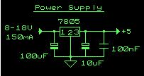
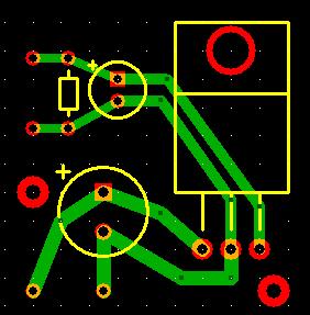
1. Power Supply allows 18 volts to be dropped down to 5 volts.
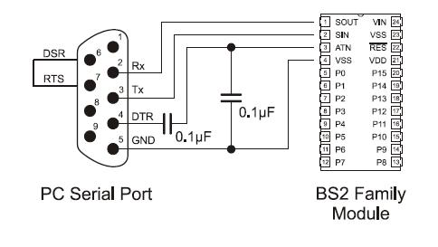
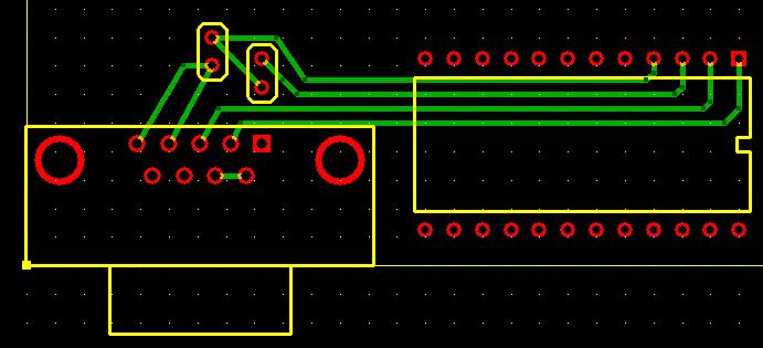
2. Programming board - Serial cable to Basic Stamp circuit
Thanks,
Phil
Please review the attached pictures.
I need confirmation of my translation from Schematic to Circuit board.
I am going to have the boards professional done, so I want to make sure this 2 sections are accurate.
1. Power Supply allows 18 volts to be dropped down to 5 volts.
2. Programming board - Serial cable to Basic Stamp circuit
Thanks,
Phil
203 x 108 - 6K
282 x 287 - 19K
484 x 273 - 20K
691 x 315 - 35K
Comments
I think, the power supply looks ok. However, you shouldn't really feed it with 18V, rather some 9V or so:
(18 - 5)V * 150mA = 1.95W power turned into heat vs. 5V * 150mA = 0.75W usable power.
Isn't that a bit of overkill to produce custom boards for such simple circuits -- unless you intend to produce many of them?
regards
adrian
I will be using a heat sink on the power supply so that I can use one for this project (2 x 9volts)
the second for a motorcycle project.
The 150ma power supply is from a document that was using a transformer power supply.
I thought if the circuit only needed, say, 55ma thats all it draws.
If that is not the case, then I need to drop 7 amps down to a usable level as well...
Thanks,
Phil
Post Edited (flying_flip) : 12/29/2008 1:41:07 PM GMT
Is the second picture going to handle the Programming component?
Thanks,
Phil
As Adrian has noted, the regulator will get pretty hot with an 18VDC input. You may need to reduce the input voltage if possible, or fit a heat sink to the regulator............................
Kindest regards
Alan
In the future when following up on a thread please post in that thread rather than starting a new one. Anyone trying to refer to your previous work would now have to search for that information.
▔▔▔▔▔▔▔▔▔▔▔▔▔▔▔▔▔▔▔▔▔▔▔▔
Chris Savage
Parallax Engineering
I'm relatively new to forum usage.
I will try to keep things together [noparse]:)[/noparse]
Phil