

analog voltage reading with BS1?
 Paulo
Posts: 21
Paulo
Posts: 21
The POT command allows for a sort of analog input by charging an RC net and timing discharge of capacitor.
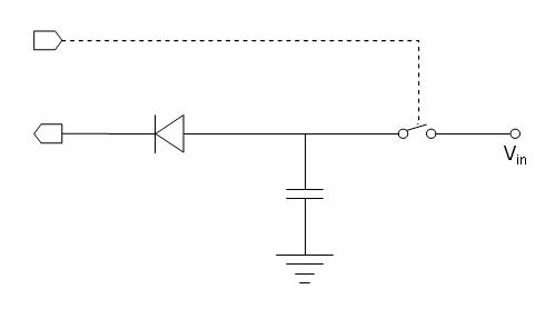
Although Application Notes bring a clever usage of an external A/D converter, I was wondering what would happen if I block the POT instruction charging phase with a diode while using another pin to control a switching device to the voltage to be measured. See attached schematic.jpg
It would be read this way:
PULSOUT switch, 100
POT input, scale, voltage
I'm am not at my shop, so I can't try it, just wonder if it would work. Next week I'll give it a try, but would appreciate any comments on the idea.
Post Edited (Paulo) : 12/19/2008 1:00:22 AM GMT
499 x 278 - 7K
Comments
Sure it required some adjustments, but the general idea works just fine.
The hardware modification was only to leave the usual resistor in series between the diode and capacitor (diode forward resistance was not enough, I guess).
In the reading software I found necessary to "seal" input pin to avoid having it sink the variable voltage I want to charge the capacitor, and providing a small delay to allow for capacitor charging.
The new circuit is in the attached figure (relay driver omitted, but sure it IS a relay). Tomorrow I'll try a FET for switching but I'm not sure it will work. A bipolar transistor will NOT work.
This is how I read the analog voltage:
Main:
LOW relay ' opens relay leaving capacitor charged with whatever voltage it got
POT input, scale,volts ' the diode blocks charging phase so it reads the external variable voltage thru fixed resistor
HIGH input ' "seals" the input by placing its voltage above the higher voltage to be read
HIGH relay ' closes relay for next reading
DEBUG volts ' display voltage
PAUSE 50 ' short delay to allow for capacitor charging
GOTO Main ' repeat forever
When I finish all testing I'll inform component values, voltage ranges, byte to voltage conversion equation, etc.
▔▔▔▔▔▔▔▔▔▔▔▔▔▔▔▔▔▔▔▔▔▔▔▔
·"If you build it, they will come."
So I sticked to the relay, even with its click-clacking noise, if I only had a reed relay at hand...
The complete circuit is attached. It has no rail-to-rail reading ability, however. Although there is no upper limit other than supply voltage (and perhaps even more with appropriate voltage divider resistors), the POT command has an inherent limitation because it stops the internal timer when the voltage drops below 1.4 V at the input pin. So the smaller voltage we can read is slightly above that, my circuit measurement range was from 1.50 to 5.07 Volt.
The measurements were pretty repetitive but far from linear. It took me some maths to regress a cubic equation that converts from bytes to Volts, and some more effort to cope with BS1 integer math limitations, but I ended up with a code that reproduces a Digital Volt Meter with an error of about 50 mV. And since it takes less than 30% of memory we can think of some practical applications.
' {$STAMP BS1}
' {$PBASIC 1.0}
SYMBOL PotPin = 7 ' 10K resistor connected to P7 via a diode
SYMBOL Scale = 87 ' scale value for test circuit
SYMBOL measure = 6 ' switching device to voltage to be measured
SYMBOL level = B2 ' storage of pot "level"
SYMBOL V = W2 ' storage for Voltage conversion
Main:
LOW measure ' opens switch
POT PotPin, Scale, level ' read external level and convert to hundreths of V
V=100*level/224*level/249*level/197 ' cubic term +9.10090e-8*level^3
V=-20*level/117*level/159/211+V ' quadratic term -1.27381e-6*level^2
V=100*level/153*248/199+V ' linear term +8.14531e-3*level
V=100*155/103+V ' constant term +1.50487
level=V/100 ' integer part
V=V//100 ' fractional part
DEBUG CLS,"Input=",#level,".",#V," V" ' display voltage
HIGH PotPin ' closes diode gate
HIGH measure ' closes switch for next measure
PAUSE 10 ' short delay to allow for charging
GOTO Main ' repeat forever
END