

Is the Prop killing my MOSFET Drivers?
 Philldapill
Posts: 1,283
Philldapill
Posts: 1,283
I'm building a high current PWM controller, driven by the propeller. It's going to have all sorts of cool features that only the propeller could do, like constant current feedback, power accumulation etc., but that's beside the point.
I am using the UCC27323 Mosfet Driver IC from TI. For some reason, when I connect even a fairly small load to my mosfets, the DRIVER, not the FETs themselves, explodes and gives a puff of smoke. I've taken the frequency down to 100Hz and almost instantly, the driver blows when a load is attached. I don't think frequency is really the issue here. I've read all the application notes about the UCC27323 and all I can find is how it keeps saying to keep the output of the driver as close to the mosfet as possible, and maybe even add a small resistor in between the output and gate. The Driver's datasheet uses a 10nF load as the testing load, while my mosfets are only 4.4nF all-in-all.
Just a little side note... When I have my mosfets on the board, and the driver, but no·load on the mosfets,·everything is fine. I see on the scope that the gates are switching just as they should. However, the moment I put a load on it, I get hit in the face with hot pieces of plastic chip casing...
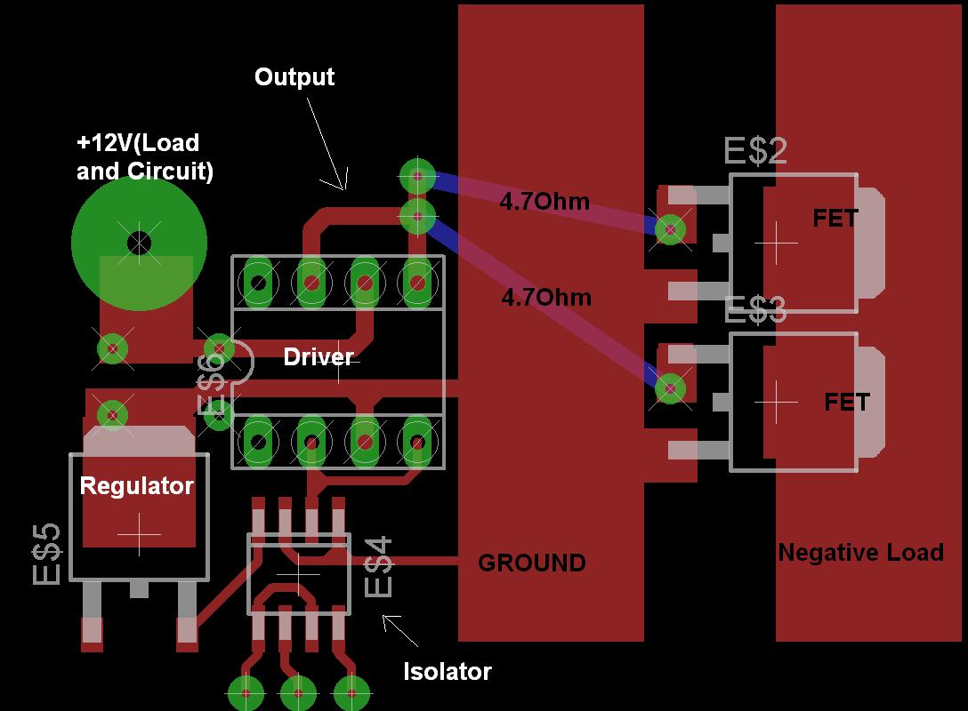
Attached is the EAGLE·board schematic I made. Sorry, I don't really make electrical diagrams for simple·circuits like this. I hope you can follow it.
Any thoughts???
I am using the UCC27323 Mosfet Driver IC from TI. For some reason, when I connect even a fairly small load to my mosfets, the DRIVER, not the FETs themselves, explodes and gives a puff of smoke. I've taken the frequency down to 100Hz and almost instantly, the driver blows when a load is attached. I don't think frequency is really the issue here. I've read all the application notes about the UCC27323 and all I can find is how it keeps saying to keep the output of the driver as close to the mosfet as possible, and maybe even add a small resistor in between the output and gate. The Driver's datasheet uses a 10nF load as the testing load, while my mosfets are only 4.4nF all-in-all.
Just a little side note... When I have my mosfets on the board, and the driver, but no·load on the mosfets,·everything is fine. I see on the scope that the gates are switching just as they should. However, the moment I put a load on it, I get hit in the face with hot pieces of plastic chip casing...
Attached is the EAGLE·board schematic I made. Sorry, I don't really make electrical diagrams for simple·circuits like this. I hope you can follow it.
Any thoughts???
1088 x 800 - 79K
Comments
Excuse my complete ignorance here, but why would you keep "as close to the mosfets as possible" yet "maybe even add a small resistor in between the output and gate".
That seems incredibly counter-intuitive to me.
I would have _thought_ (and remember I'm uneducated in anything electronic - "would you buy a transistor from this man??") that keeping things close together would be to minimise resistance and capacitance, but adding a resistor would do exactly the opposite.
Someone hit me with the clue stick please!
▔▔▔▔▔▔▔▔▔▔▔▔▔▔▔▔▔▔▔▔▔▔▔▔
Cardinal Fang! Fetch the comfy chair.
The reason for the small resistor in between, is to reduce the "Q" of this natural RLC circuit. I thought the same as you did at first, "Isn't the goal of the driver to charge/discharge the gate as QUICKLY as possible?". The resistor DOES in fact reduce effiency directly, but it also indirectly aids in keeping the circuit stable by reducing any oscillation between the gate and stray inductance.
As for the explosions, I just tried something a little different(added another bypass cap), and this time the top of the chip literally hit the ceiling. Something is wrong... The funny thing is, I have another circuit with essentially the same setup, and it works just fine. I am running one of these tiny TO-252 package mosfets at 30kHz, 5A and it's not even warm, nor is the driver.
▔▔▔▔▔▔▔▔▔▔▔▔▔▔▔▔▔▔▔▔▔▔▔▔
· -- Carl, nn5i@arrl.net
opto-isolator could be causing a slow rise/fall time being applied to the input
of the mosfet driver. The internal translator circuits could be driving OUTA
high before OUTB resulting in cross conduction.
Just a thought.
As for the Isolators, I should have specified. These are no opto-isolators. These are the ISO721 digital 150MBPS isolators from TI. They are extremely fast. I think their rise and fall times are faster than the driver itself!
As for the cross conduction, I doubt it... The datasheet explicitly says it is just fine to parallel outputs/inputs in this way. My original board was using a UCC27322 which is a 9A, single output version. I was getting the same results(failures), and that is why I actually switched to the 4A, dual driver version. Apparently, same problem.
Thanks guys. Even if I shoot your ideas down, they help me look at the problem from another angle, and I appreciate it.
Problem still has yet to be solved.
▔▔▔▔▔▔▔▔▔▔▔▔▔▔▔▔▔▔▔▔▔▔▔▔
· -- Carl, nn5i@arrl.net
1. If you're using an opto-isolator, yes, it may well be too slow (rf: scotta). What is the part number?
2. If your 12V power is connected on the lefthand side of the board, as you indicate, you've got motor current returning through that skinny trace under the driver. This is not good, because it will alter the voltage that the driver sees on its supply terminals. You need to cut that trace where it joins the groundplane and run a wire directly from the power input to the groundplane.
3. Are you using protection diodes across your load? If not, you may get dangerously high transient voltages feeding back and killing your driver.
4. Always use bypas caps (rf: scotta)! Also, depending on the size of your load, you will require a large (1000uF or more) electrolytic cap where the power comes into the board.
-Phil
1. The isolator is not an opto-isolator. It's rated for 150MBPS, and is faster than the driver itself. It is an ISO721M digital Isolator from TI.
2. Under these test conditions, I am using an old headlight that draws about 7.2A under a 12.65V Battery. There should be minimal inductance in the lamp. As for the skinny trace on the board, I don't know where the current would be going - The Negative terminal of the battery is connected to this GROUND Plane with a good sized clip. I see your point about the possible elevated voltage where the trace meets the plane, but I have these traces coated in thick solder and I really don't feel that it is causing that much of a problem... I have a bypass caps all over - 0.1uF ceramics at each device, and 100uF at the driver as well, plus a 1000uF cap at the supply which isn't shown in the diagram because it was an after thought once I made the board(durrrrr).
3. No, I am not using protection diodes on THIS board. My previous one in which I used the 9A version of the chip, yes I did use a 2N1007 diode, but it may not be fast enough. Regardless, it still blew with the old board.
4. Bypass caps are everywhere.
-Phil
▔▔▔▔▔▔▔▔▔▔▔▔▔▔▔▔▔▔▔▔▔▔▔▔
'Just a few PropSTICK Kit bare PCBs left!
I'm sure the gates are NOT shorted to ground or supply. The circuit works just fine when no load is attached, but the momeny I attach CERTAIN loads, it goes poof. I've just found that when I put a 1Ohm resistor across the Positive Supply and Drain of the mosfet, it works fine, gets warm, and hums at 1kHz, as it should. The resistor is pulling around 12A, but when I put the headlight in the same configuration, it goes poof. The headlight pulls about 6A directly connected to the battery.
I learned this back in the late 50's when my lamp drivers failed way sooner than expected. Plotting with low current, found tungsten had quite a low cold resistance vs. that when at rated voltage and current. Nature and it's many surprises.
▔▔▔▔▔▔▔▔▔▔▔▔▔▔▔▔▔▔▔▔▔▔▔▔
Harley Shanko
Leon
▔▔▔▔▔▔▔▔▔▔▔▔▔▔▔▔▔▔▔▔▔▔▔▔
Amateur radio callsign: G1HSM
Suzuki SV1000S motorcycle
-Phil
▔▔▔▔▔▔▔▔▔▔▔▔▔▔▔▔▔▔▔▔▔▔▔▔
'Just a few PropSTICK Kit bare PCBs left!
@Leon,
Sorry about the bad schematic. It's a pretty simple circuit. I'll attached a circuit diagram in a minute.
@Phil,
Yes, I've tried that. I modified my psmAsm file so that I have 0-1000 duty cycle control, rather than 0-100. I started at 5(0.5%) duty cycle, and it did the same thing. Lots of smoke, and a racing heart rate.
The second thing that can happen, is when driving an inductive load, each time the mosfet turns off, there is a voltage spike. At lower frequencies, this is probably not too bad, but at high frequencies, the repetitive voltage spike can damage components such as diodes by overheating them.
Also, I forgot to add, there are plenty of solutions for flyback from inductive loads and it looks like you have used some of them already (filter caps, diodes, opto-isolation, etc..), I don't that that is your problem here.
Post Edited (soshimo) : 12/18/2008 1:18:14 AM GMT
-Phil
▔▔▔▔▔▔▔▔▔▔▔▔▔▔▔▔▔▔▔▔▔▔▔▔
'Just a few PropSTICK Kit bare PCBs left!
BTW, what gage wire — and how long — comes from the power supply to the board?
-Phil
▔▔▔▔▔▔▔▔▔▔▔▔▔▔▔▔▔▔▔▔▔▔▔▔
'Just a few PropSTICK Kit bare PCBs left!
I always thought that the gate capacitance and current into the gate was independant of the load Drain-Source Current.
By the way, I changed out my resistor from the driver to the gate. I put a 124Ohm in the 4.7Ohm's place. Same thing, no change. I'm starting to wonder if there is something causing the internal circuitry of the driver to turn both sides of it's bridge on at the same time. With the 124Ohm resistor in place, the MAXIMUM current into the gate from the driver, even if it were shorted, would be 12.6V / 124Ohm = ~101mA. I seriously doubt this could possibly be causing the driver to blow instantly. I've found that when one of these blow, they aren't hot to the touch, which makes me think there is an internal short that is extremely fast, but builds enough pressure to blow the device apart, stopping the short before any heat can accumulate.
Post Edited (Philldapill) : 12/18/2008 2:15:02 AM GMT
Now, the cause of this is still a mystery, but I now have about a 315Ohm resistor between driver and gate, and it seems to work like a champ, yet my mosfet now gets pretty warm at higher frequencies(above 30kHz)... [noparse]:([/noparse]
-Phil
▔▔▔▔▔▔▔▔▔▔▔▔▔▔▔▔▔▔▔▔▔▔▔▔
'Just a few PropSTICK Kit bare PCBs left!